Due to the weight and size of my 65 Vibrolux, I decided to replace it with a Princeton 65 Solid State. It works well considering it's a disposable amplifier; however, the distortion channel is rather hissy, especially at higher gain levels, where the amp shines somewhat.
Looking at the schematic, two problem sources are evident. The first one is high resistance into the non-inverting input of U2A. The other problem is that U2 is a bipolar opamp. Perhaps a JFET input type may help, but the total of all those resistors will still be an issue. I know this from past experience.
To remedy the high resistance is not as simple as reducing resistance values and increasing capacitance values for the equivalent roll-off, because of the U1A circuitry. I have never seen anything like this before. It is not readily intuitive, at least for me.
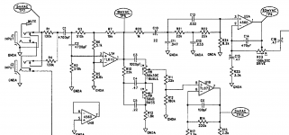
Would anyone have an idea that doesn't require completely redesigning the input section? I would consider substantial modifications to the board, however. Here's a blowup of the input area:

Here's the entire schematic:
View attachment Princeton_65_Schematic.pdf
Any suggestions are appreciated.
Looking at the schematic, two problem sources are evident. The first one is high resistance into the non-inverting input of U2A. The other problem is that U2 is a bipolar opamp. Perhaps a JFET input type may help, but the total of all those resistors will still be an issue. I know this from past experience.
To remedy the high resistance is not as simple as reducing resistance values and increasing capacitance values for the equivalent roll-off, because of the U1A circuitry. I have never seen anything like this before. It is not readily intuitive, at least for me.
Would anyone have an idea that doesn't require completely redesigning the input section? I would consider substantial modifications to the board, however. Here's a blowup of the input area:

Here's the entire schematic:
View attachment Princeton_65_Schematic.pdf
Any suggestions are appreciated.
The input is a modifies Sallen-Key high-pass filter for about 100Hz. This is not a bass amp.
Fuzz/distortion usually involves boosting the gain so any noise is accentuated. The best idea is a noise gate.
Any instrument input needs to be (very) high impedance so reducing the resistance is not a great plan. Loading a guitar pickup coil inductance kills the highs and loading piezo pick-up kills the bass. You need a meg-Ohm input impedance.
You may want to consider a discrete FET buffer.
PS: Q2,Q3 (as per the pdf schematic) are some kind of gate or compressor in the distortion channel. My guess is compression/sustain, which will exaggerate noise/hiss. You could modify this circuit to add a noise gate function. You need to bias the gates off (negative) and remove that bias in the presents of input.
PPS: There is also Q4 which could also be used to gate the distortion channel.
Last edited:
I think I would exhaustively check mechanical items like shielding, soldering, switches, jacks before changing the circuit. Just because the hiss is worse at higher gain doesn't mean it is being generated by the high gain portions of the circuit.
That's it! FET Opamp buffer at the R1 C4 C1 junction with 1M input impedance. There's plenty of room in the chassis. The 130k input resistors and both the 510k have to go. The caps will have to be adjusted accordingly. Hopefully, the high value resistors can be reduced to around 10k or so.....You may want to consider a discrete FET buffer.
Thanks.
This is prudent. I will do this first while beefing up the anemic power section heat-sink, which is why so many of these burn out.I think I would exhaustively check mechanical items....
Thanks for that, I probably would have forgotten.....
That's it! FET Opamp buffer at the R1 C4 C1 junction with 1M input impedance. There's plenty of room in the chassis. The 130k input resistors and both the 510k have to go. The caps will have to be adjusted accordingly. Hopefully, the high value resistors can be reduced to around 10k or so.
Thanks.
IMHO that's pointless, the TL072 is a FET input opamp.
The first element of the drive channel is U2A which is a 4560 BJT.IMHO that's pointless, the TL072 is a FET input opamp.
The first element of the drive channel is U2A which is a 4560 BJT.
No, look again. 5mV does not become 19mV with passive components hahaha!
LOL! The TP8 test-point balloon threw me off. Good looking out.No, look again. 5mV does not become 19mV with passive components hahaha!
However, the non-inverting input of U2A is met with 700k of total resistance, generating significant voltage noise. Does this disappear just because the chain is interrupted by the output of U1A?
By this reasoning, the same would go for 22k R21 R22 shunted by the 8.2k R24. So there are geniuses at Fender.Yes, the output of U1A is low impedance, forget your previous reasoning completely.
Still looking to reduce the hiss without a gate.... The clean channel is very quiet, and the drive channel only starts to get annoying around 7 on the drive pot; 9-10 is brutal.
It could still be a cold joint or a bad component I suppose, as suggested before. I will push around with a stick first, then ground the input of U2A and go from there.
It's not the guitar, btw. It has a buffer and has been proven to be "noiseless" at any guitar volume setting.
Might I ask how you know the guitar is "noiseless", which is actually a theoretical concept only? What buffer and where?
Hiss in a guitar chain is not trivial to eliminate, unless it's caused by a failure of some kind.
Hiss in a guitar chain is not trivial to eliminate, unless it's caused by a failure of some kind.
Again, how did you come to the conclusion that the guitar was noiseless?
A DIY component like your buffer is much more likely to be the cause of issues than a commercial product like the Fender. I would review the shielding details from whatever source you got the design, or just Google for further tips. I would throw a bypass cap on the lower leg of the resistive divider at the input of the TL071 as one thing to try.
A DIY component like your buffer is much more likely to be the cause of issues than a commercial product like the Fender. I would review the shielding details from whatever source you got the design, or just Google for further tips. I would throw a bypass cap on the lower leg of the resistive divider at the input of the TL071 as one thing to try.
That buffer solved all noise the guitar was generating, including the hiss you get when the guitar volume pot is at midpoint resistance, when the pot was reduced to 25k. The cavity is shielded with copper foil. It works flawlessly.Again, how did you come to the conclusion that the guitar was noiseless?
A DIY component like your buffer is much more likely to be the cause of issues than a commercial product like the Fender. I would review the shielding details from whatever source you got the design, or just Google for further tips. I would throw a bypass cap on the lower leg of the resistive divider at the input of the TL071 as one thing to try.
One would only need this when playing through high gain amps and insist on low hiss without a gate. The bummer part is a battery is needed. I put a quick change box in the body which many cringe at the prospect. If there is room in the cavity, the box could be installed there, then the axe could be returned to original with a new cover.
You reduced the pot to 25K, and THEN added a buffer to fix the hiss that that generated?
Frankly, I still suspect some basic error is being made.
If you insist, you can probably tweak the gain structure to see if that fixes the hiss. Maybe add a little gain at the buffer, maybe add a little at U1A, and reduce at U2A.
Frankly, I still suspect some basic error is being made.
If you insist, you can probably tweak the gain structure to see if that fixes the hiss. Maybe add a little gain at the buffer, maybe add a little at U1A, and reduce at U2A.
On the guitar buffer, the volume pot(s) is driven by the low impednce opamp. Reducing from 500k to 25k eliminated the slight his from the 500k pot itself, and that only was heard at mid-point resistance, about 6-7 on the dial. The noise from the pickups was already gone.You reduced the pot to 25K, and THEN added a buffer to fix the hiss that that generated?
Frankly, I still suspect some basic error is being made.
If you insist, you can probably tweak the gain structure to see if that fixes the hiss. Maybe add a little gain at the buffer, maybe add a little at U1A, and reduce at U2A.
On the amp, your idea is probably good. I tried that boost/reduce technique on a noisy fuzzbox and it worked perfectly.
I won't be opening the chassis tonight, but I will report anything found soon. I watched a couple of YT vids on this amp in OD and hiss was heard, and I doubt they had the drive all the way up.
Thanks for the idea.
U2 was replaced with OPA2134 and is notably quieter. The only way to reduce hiss further is with the boost/reduce. G=3 and 1/3 divider works and stays away from rail clipping. U2 comprises the first two stages of the Drive channel, and that's where the majority of hiss is generated in my experience.
Replacing the red diodes with 4148 might reduce the noise somewhat and also lower the output a little; this is a lot easier than adding an opamp. The board traces are very thin.
The heat-sink design is good. However, they use silicone grease as the heat-conducting compound. It's possible they blow up because guys add a second cabinet in parallel which probably brings the load to 4 Ohms. I saw one of these for sale with a jack, L-bracket mounted on the back.....
A factory incomplete solder joint was found at one of the input jacks. It was intermittent as well. Quiet as graveyard now. Thanks.I think I would exhaustively check mechanical items like shielding, soldering, switches, jacks before changing the circuit. Just because the hiss is worse at higher gain doesn't mean it is being generated by the high gain portions of the circuit.
- Home
- Amplifiers
- Solid State
- Fender Princeton 65 SS Wierd Input Section

