I've addressed the "output too close to the rail" problem by putting regulators on the +14 supply to make another supply +3.5 to +11. The CMOS logic runs on that supply, with input states of <1/3 Vcc off and >2/3 Vcc on. Between is maybe and should not occur. Now using two 5534 as DC adders adding & subracting 150 to 200 mv to input voltage, 393 as comparator of 2 op amps driving CD4093 nand logic. CD4093 should provide 5 v swing to nfet gates at 200 ma current for relays.The 324 (358) input stage is exactly what you want for comparators. It common modes down to the negative rail (ground for single supply) and tolerates high differential input voltages without a large change in input current. The other useful feature is that it’s output will go to zero (or negative rail) in the low state.
I'll reiterate all the advice here: if you want a comparator, use a comparator. Comparators and opamps are hugely different, in particular comparators are many orders of magnitude faster to slew as they have no compensation, and they come out of saturation inordinately quicker (its their sole job, basically, to de-saturate and slew).
Also opamp slew rates may not be fast enough for reliable driving of high speed logic inputs, leading to multiple transitions being seen by the logic device. 11V/µs is glacially slow to a CMOS logic input, which are expecting more like 1V/ns transistions.
As a corollory a comparator used with negative feedback will not amplify, it will oscillate! Comparators usually draw much less power than opamps.
For a window comparison you can use a wired-AND gate on the outputs of two comparator sections directly to generate a logic signal indicating deadband, since they are open-collector.
The practical upshot is if you don't already have some LM339's in stock, get a few on the next order, they are cheap as anything quad comparators of decent spec [ but note the pinout is different to quad opamps ].
Msg received, op amps make bad comparators, even if you don't need rail to rail voltage swing.
I'm building gnobuddy's scheme in post #18. First trial will be 4558 but have sockets if only TL082 will do. Seems to be 3 state out of the third op amp; I'll have to build some logic to turn forward & reverse current source scheme posted into run and reverse current source the existing device relays use. AND gates are not common in 14 v logic but Nor & Nand 4025 & 4093 CMOS gates are in stock. Have 393 single comparators, not ideal since they don't pull up, require a resistor, but no newark/digikey parts orders will be put in this month. It may require two 393's to determine forward & reverse logic signals, and a wire or of the two to drive the darlington transistor that drives the run (either way) relay. Gnobuddys suggested reverse transistor & zener blocker can run the reverse relay direct.
Cost of a parts order is not the $.80 part, it is the $12 freight bill+the minimum buy to avoid a handling charge. Bought 200 $.07 LED's from a surplus house for CCS bias since Newark only stocked red+green at $.85 each when I was ordering LED's. Soldering 16 1n4148 for 8 CCS was tedious. Paid freight bill from surplus house with a package of 3M 8214 respirators which put order over free freight minimum.
The good news of the night, only 1% of covid-19 patients die. Only the old, the diabetic, the HBP (me, me, me).
Last edited:
https://www.analog.com/media/en/technical-documentation/application-notes/AN-849.pdf
It's not an absolute rule, never use opamps as comparators. But usually better with a for-purpose comparator. Especially here where you have many many other details to troubleshoot before your motors whirrr smooth and reliable.
It's not an absolute rule, never use opamps as comparators. But usually better with a for-purpose comparator. Especially here where you have many many other details to troubleshoot before your motors whirrr smooth and reliable.
The op-amps are used as op-amps in this circuit (not as comparators), so there shouldn't be any special demands on them. I used TL072 in the simulation simply because I happened to have an LTSpice model for it on my computer. But its not critical.I'm building gnobuddy's scheme in post #18. First trial will be 4558 but have sockets if only TL082 will do.
The op-amp output itself is linear, but the combination of zeners and NPN/PNP transistors at the output converts that to three-state. If the op-amp output is near half Vcc, neither zener turns on, so neither relay switching transistor turns on.Seems to be 3 state out of the third op amp;
I suggest interfacing the two output transistors I designed into my circuit directly with your existing relay drive circuitry. That may require an intermediary single transistor if you need to invert the logic, but there will be no need for 14V logic, or digital gates of any sort.AND gates are not common in 14 v logic
Yeah, this frustrates me too. Eventually I realized that driving to the nearest electronics store that actually carries anything I want also costs about $12 - in gasoline!Cost of a parts order is not the $.80 part, it is the $12 freight bill+the minimum buy to avoid a handling charge.
-Gnobuddy
The two transistors shown are suitable for an actuator having forward and reverse relay inputs. The device apparantly has run and reverse inputs. A couple of 4093 nand gates would have sorted that out, but the CMOS maybe zone between 1/3 & 2/3 input voltage means they could oscillate when the motor is supposed to be off. As one transistor is at top of relay and other is at bottom, can't use one diode to or reverse into run relay. May have to use two 393 comparators to decide forward and reverse, then use nand gate to turn that into or (forward or reverse = run). I'm not sure, it is hard to read the blueprint, one reason I gave up on repairing the replacement control board. There is a big TO3 darlington npn transistor on a huge heat sink driving "run" relay I think, then the reverse relay drive apparently comes out of two TO92 transistors used as a darlington.I suggest interfacing the two output transistors I designed into my circuit directly with your existing relay drive circuitry. That may require an intermediary single transistor if you need to invert the logic, but there will be no need for 14V logic, or digital gates of any sort.
-Gnobuddy
Don't have 9 v zeners, using a stack of yellow LED series 6.8 v zener to simulate 8.4 v zener. Problem now is that my "12 v" home power supply is putting out 18.4 v, so current will flow all the time through the double stack zeners. Have to load it down somehow. Actual organ power supply is regulated to 13.5 to 14 v by 8 parallel 2n3772 transistors.
First cut I'm using 3900 deadband resistor instead of 2000 ohm. I can easily tack a parallel resistor on top to lower value, whereas removing and replacing resistors can lift land off the project board. I'm going to use two DVM to determine how big the dead band is, and whether it stays constant over the .6 to 4.8 v input range. Reason for yellow led, I don't have a 3rd meter to determine what the transistor stack is putting out.
Driving to my nearest parts store would be a 330 mile trip. If there is a Fry's in Chicago. I'd have to rent a car, too, I don't run one anymore.
Last edited:
I thought "run" meant "run forward", while "reverse" meant, well reverse. Evidently I misunderstood. Sorry!The two transistors shown are suitable for an actuator having forward and reverse relay inputs. The device apparantly has run and reverse inputs.
So: you have to turn on both the "run" and the "reverse" inputs simultaneously when you want the motor to run backwards, correct?
That's an easy fix. All you need is to add one diode and one resistor to the existing circuit. Schematic attached. No CMOS or comparators needed at all. 🙂
D6/R3 turns on the "run" relay any time the "reverse" relay is actuated. D6 blocks any current to the reverse relay when the forward relay is enabled.
It's too bad that electronics stores have almost all bitten the dust. Music stores that sell band instruments are following suit. Guitar stores are still in business, for now.
-Gnobuddy
Attachments
Last edited:
I'm still guessing as to how these are actually wired. I'm working in the dark, so I cannot give you a drop-in solution, only a starting point....The device apparantly has run and reverse inputs...
But if you can trace the schematic (just the existing circuitry around that motor and relays) and post it, I can tweak my design to interface with your existing circuitry, without your having to modify anything.
-Gnobuddy
Thanks again. Your diode to base of Q2 is elegant. Unfortunately, both bottom sides of the coils of the two relays are common to minus 14 v. As I lay on my belly to work on the device under a pipe chest 36" off floor, I'm trying to avoid rewiring that. Organ supplier tends to wire relays/solenoids with a 300 W electric iron, so I'm not confident of moving the wiring around with my iron reliably. Also, pipe organs always put the relay coil flyback diode on the electronics board instead of on the relay. Since 1n4001 didn't get under $.10 until ~1965 and lots of pipe chests full of solenoid valves are in use that are older than that. Yes, run has to be on, positive current flow in wire, at same time as reverse. I think. Not expecting package solution. Looked again at op amp inventory, have 4 in 1 339 comparator ICs instead of 393, so plenty of those in one IC. Spent day making a new 12 v power supply, installing 680 ohm resistor+yellow LED+6.8v zener resistor twice stack, disarming the 4th op amp of 4558 from oscillating, mounting DIP project board to bare transistor/power board. Buzzed the wiring.
Since not confident I can get more than 6 ma out of 4558, and they swing voltage pretty well, & beta 20*6ma is 120 ma out of a TIP31C or 32C, planning to use generic nfet & pfet to switch relays 1st case. 5 v across 680 ohms & yellow LED should turn on gate. Pfet (IRF5210) hangs source on the + rail, drain to the relay coil. gate to junction top yellow led & 6.8 v zener Nfet source goes to lower relay coil. Gate to junction bottom LED & 6.8 v zener. Wish GEDA (linux schematic drawing pgm) wasn't such a PIT* to use would draw it. Will take control board over to church this week after select dead zone resistor and try first with fwd & reverse relay drives from *fets, (which I don't think will work, but relay wiring is not on the blueprint they gave me). Shouldn't hurt anything, if motor runs forwards & not backwards then my suspicions about run & reverse would be confirmed. Nfet & pfets have flyback diode in the transistor, anyway. thanks again.
Since not confident I can get more than 6 ma out of 4558, and they swing voltage pretty well, & beta 20*6ma is 120 ma out of a TIP31C or 32C, planning to use generic nfet & pfet to switch relays 1st case. 5 v across 680 ohms & yellow LED should turn on gate. Pfet (IRF5210) hangs source on the + rail, drain to the relay coil. gate to junction top yellow led & 6.8 v zener Nfet source goes to lower relay coil. Gate to junction bottom LED & 6.8 v zener. Wish GEDA (linux schematic drawing pgm) wasn't such a PIT* to use would draw it. Will take control board over to church this week after select dead zone resistor and try first with fwd & reverse relay drives from *fets, (which I don't think will work, but relay wiring is not on the blueprint they gave me). Shouldn't hurt anything, if motor runs forwards & not backwards then my suspicions about run & reverse would be confirmed. Nfet & pfets have flyback diode in the transistor, anyway. thanks again.
Last edited:
What do the other ends of the relay coils go to?...both bottom sides of the coils of the two relays are common to minus 14 v.
I see you mention N-channel MOSFETS later, I was going to suggest something similar...but watch out, turn-on voltage for a MOSFET is usually several volts, while a BJT needs maybe 0.7 volts.
If the op-amp output swings to, say, 1.5V, and you have a 14V supply, that leaves 12.5. If the MOSFET wants 5 volts of that to turn on, the zener shouldn't exceed 7.5 volts.
The gate-to-source resistor for the MOSFET can be considerably bigger than the 560 ohms I suggested for BJTs; you don't need super-fast switching, so you can easily use 10 kilo ohms or more here. (It will take longer to drain gate charge out of the MOSFET, so switching will be slower, but still millions of times faster than the motor relays.)
I use LTSpice (it runs on Wine in Linux) for quick-n-dirty schematics, Kicad (also on Linux) when I want them prettier. I haven't tried GEDA, but if it's awkward, you might find LTSpice good enough for quick simple schematics....GEDA...such a PIT* to use...
That's definitely handy!Nfet & pfets have flyback diode in the transistor, anyway.
And you're welcome. I hope you get it all sorted out and working!
-Gnobuddy
Went over to the church yesterday to measure the board to see how much board to saw off (1.2") to fit in the case. Also looked at the blueprint again.
Both relays have the top attached to +14. Run relay bottom connected to collector of a darlington npn, emitter to PS return. Reverse relay bottom connects to a npn collector on the drive board, emitter to PS return.
voltage swing of red led series 680 ohms in the stack at 6 ma into op amp is 5 v. So that should turn on/off a pfet at one end and a nfet at the other end. Can use the higher current of the pfet through a base resistor to force current into the run darlington. Nfet can drive through base resistor a npn (TIP31c) to pull down rev relay. Logic OR to turn forwards into run with reverse is still TBD.
The forward & reverse LED's are lighting at opposite ends of my simulated position pot, with small a dead zone in the middle where both LED's are out. I have miswired the top of the position pot that the top end doesn't go to +rail-3v so the position dvm says wiper voltage is zero at all times. So I can't measure dead zone in voltages yet. Will try to find that miswire today. Thanks for the "servo" circuit which seems to provide 3 states, for, rev, stop, just based on pot resistance.
If relays are 24 v coil, using the -12 chopper supply that started the fire that I am abandoning for lower return, will do all motor drive with fets. Have lots of those, the nfets are free salvage from numerous blown PCAT power supplies. Have six pfets which were $1.44 each.
Last edited:
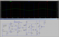
Do the relay connections in the attached image look right? (Q2 & Q3 being the existing NPN power Darlington transistors driving the relays in the organ.)Both relays have the top attached to +14.
<snip>
Run relay bottom connected to collector of a darlington npn, emitter to PS return.
<snip>
Reverse relay bottom connects to a npn collector on the drive board, emitter to PS return.
If so, the schematic in the image should do the trick. The only change is that the signal to turn the "Run" relay on (R14/D5) is now taken from the collector of the PNP driver (Q1) rather than straight from the relay coil.
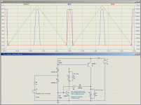
The waveforms show that things are working as they should - when the red line (reverse relay current) jumps up to maximum, so does the blue line (run relay current). The red and blue lines almost overlap, but if you look closely you can see that they are both present.
-Gnobuddy
Attachments
Thanks, post 32 is nice & simple. Q2 can be the existing TO3 darlington npn transistor, I think.
Led's in the stack reflect reality I think. I must have had the meter in hold last night for everything to be zero. With R1 @ 3900 ohms, from very dim led to other very dim led is about a .5 v movement of the position pot. BTW the U3 is sourcing/sinking about 1.05 ma at that point. Op amp output is 2 v from the rail, I would have thought it would put out more current there. I have R11 at 680 ohm to protect op amp from overcurrent. R9 & R10 are at 680 ohm, D1 & D2 are red LEDs series two 6.8v 1.3w zeners. That is what I get for buying 100 "yellow" LED from a surplus house, but these were $.06 and the yellow ones from newark were $.85. Will take base drive for Q2 & Q3 from the junction of the zener & the LED for a little more voltage swing.
Will try lowering R1 to 1950 ohms to try to lower dead band a little.
Sorry I'm so slow. Weather was nice to day & wheel bearing on my last ride was thumping. Took the power wheel off, lots of unwiring, put on an old fashioned wheel while I try to remove & purchase bearings.
Last edited:
Reducing R1 to 1930 ohms reduces the dead band on the position pot to about 0.3 v. That is when from one led just lights til the other led just lights. Will try that. Will make a darlington npn out of Q3, too. 1.05 ma drive current out of op amp is not very much. Might get a little more drive current with upper voltage at 14 instead of the 12 I'm getting out of this home power supply. Thanks again.
I played with a model airplane servo in an attempt to make a voltage controlled potentiometer. Some difficulty making an adapter to complete the mechanical connection. An ebay module converted a 0 - 5V control signal to whatever control protocol the RC folks use, virtually min and max angular position.
Connect that to the instrumentation amp front end and I'd think you could control the potentiometer position as a function of those two slow signals directly.
Something like this could be used with the long time constant servo to bias a tube amplifier by physically turning a potentiometer. With the servo time constant cap justifiably NOT in the signal path of the music - the potentiometer is.
There's a little gear whine when these things move, so taking care in mounting the servo and enclosing the connected combo are probably further considerations.
Last edited:
It certainly isn't! Something is wrong, unless you're using some sort of ultra-low-power op-amp. What op-amps are you using?1.05 ma drive current out of op amp is not very much.
I just took a quick look at a TL082 datasheet, and while it didn't list short-circuit output current, it showed +/- 12.5 volts being delivered to a 2k load using +/-15V rails. That would require +/- 6.25 mA output current, so we know this particular op-amp can put out at least that much.
Op-amps aside, remember, your LEDs drop about 2 volts each, much more than the single 0.7V Vbe I originally planned for. Because of this, some resistors may need their values tweaked.
As before, it would help if you posted a schematic of what you actually built - no need for GEDA, just a quick hand-drawn schematic on a piece of paper and a digital camera to photograph it will work fine (and it's much quicker!)
-Gnobuddy
It's a very simple form of PWM, dating back to WWII or so. A stream of 5V logic pulses, roughly 20 mS apart. 1.5 mS ON time centers the servo, 1 mS is nominally full counter-clockwise, 2 mS is nominally full clockwise. Different manufacturers tweak these endpoint values a bit from the standard....model airplane servo...whatever control protocol the RC folks use...
What's funny is that inside the servo is - a potentiometer, turned by a heavily geared-down little motor! The internal servo electronics compare the potentiometer's wiper voltage with a DC voltage derived from the incoming pulse train, and tell the motor to rotate until the two are equal.
In short, inside the potentiometer is exactly what Indianajoe wants! Except the motor is tiny and the drive electronics won't cope with 14 volts and 4 amps.
For a brief moment early in the thread, I thought that cannibalising a bit RC servo might be the simplest route to solving the OPs problem - but tiny SMD servo boards are not easy to re-work, and big RC servos are very expensive, so I dropped that idea quickly.
If I put on my analogue hat, I would bet my boots that a 555 timer and an RC servo can be made to do pretty much what's wanted here.
Last summer I decided to go digital and use several hundred million transistors to drive a servo instead of the handful in a 555 - I used an Arduino to build an automated cat-feeder. 🙂
-Gnobuddy
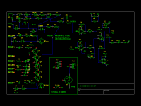
Here is the GEDA schematic so far. Driver transistors not installed yet. Think low current on 620 ohm resistors in stack comes from using 12 v power supply instead of 14 v in actual device. The top & bottom 620 ohm resistors in stack are swinging 0.63 v which is 1.05 ma. Will have to increase value of those resistors, or find an actual 14 v power supply, to drive base of any switching transistor Q2 Q3 from on to off.It certainly isn't! Something is wrong, unless you're using some sort of ultra-low-power op-amp. What op-amps are you using?
As before, it would help if you posted a schematic of what you actually built - no need for GEDA, just a quick hand-drawn schematic on a piece of paper and a digital camera to photograph it will work fine (and it's much quicker!)
-Gnobuddy
Voltage drop on red LED's is about 1.2 v. The other supply I have working is a 12 v battery charger putting out 18.4 v at no load. That would light up both led in the stack all the time. Frame is covered with terminal strips, would have to repackage it in a bigger box to put a regulator on it.
The digital camera I bought from newark came with a unpurchaseable battery. Which is now dead.
What forum do you talk about arduino on? I bought one to do this from mcmelectronics, the month before newark shut them down. So I didn't get the assembler or product info downloads. So far no compiler or assembler has worked since Intel 8080 development system in 1978. My IT department (me) doesn't spend enough money on op systems to ever buy any compiler that matches my PC. So they always sit there with a blank screen doing nothing.
Thanks for the interest.
Attachments
Last edited:
That will certainly make a difference, but you have also inserted a 680 ohm resistor in series with the op-amp output, which is not in my schematic.Think low current on 620 ohm resistors in stack comes from using 12 v power supply instead of 14 v in actual device.
There's no need for that resistor, because the op-amp will have short circuit protection at the output, which will limit output current to a safe level. The zeners (and the LEDs you added) will drop most of the supply voltage, so there won't be excessive power dissipation in the op-amp while the output is shorted, either.
I suggest either removing that 680 ohm resistor entirely, or jumpering it with a much lower value resistor, to see if that gets you enough drive for the transistors. You can also increase those 620 ohm resistors, but the LEDs will get dimmer if you do.
I didn't join any forum, just did a few Google searches to get started.What forum do you talk about arduino on?
The only tricky coding part with my project (automated cat feeder) was the need for a real time clock - I don't want the cat to go hungry because the mains power failed for a moment, and the Arduino lost track of time! Fortunately, I found a very nice tutorial on Adafruit.com, and they sold the RTC chip I used as well.
Speaking of Adafruit, any tutorials you find there are going to be good. Lady Ada, aka Limor Fried, founder of Adafruit, is the real deal, an MIT grad with degrees in EE and Computer Science.
I moved entirely to Linux in my personal life starting in 2001, and the last 19 years have been much more pleasant for me than for most people, who have had to struggle with nightmarish problems with endless Windows insecurities, Android spyware, Apple spying and control, ransomware, etc. So my operating systems are zero-cost (currently Xubuntu 18.04), and so is all the software running on them.no compiler or assembler has worked since Intel 8080 development system in 1978. My IT department (me) doesn't spend enough money on op systems to ever buy any compiler that matches my PC. So they always sit there with a blank screen doing nothing.
There is a very nice IDE (integrated development environment) for the Arduino, created by the founders of the Arduino itself, and that's what I used: Arduino - Software
I don't think you need any special or powerful PC hardware, just a USB port. At work I still use a few ancient netbooks with Intel Atom CPUs for tasks like this - they work fine. I think they're a decade old or more.
When I lived in the US, perfectly usable computer hardware was often to be found free on Craigslist, or sitting by the trash-bins on recycling day.
-Gnobuddy
- Home
- Live Sound
- Instruments and Amps
- 5534 as comparitor with dead zone