On a more serious note. How come no one is launching AES67 DACs on the home audio market? Are people scared of cat5E cables or something?
On a more serious note. How come no one is launching AES67 DACs on the home audio market? Are people scared of cat5E cables or something?
Probably because most in high end audio are incapable of writing software and the cost to license existing modules or drivers may be high.
It was explained to me that Luxmans are designed to satisfy demands of the Japanese audiophile market. They tend to look for certain features in audio products, including high frequency looking components and likewise looking design features such as PCB traces.
Could be. I wondered if there was more money in USB cleaning fudboxes than considering if there was a better way. My server has a spare NIC so for me would be a good solution. Ah well, my use cases are odd anyway.
Current best practices for EMI are to use a ground plane instead of a star. For low level high gain stuff its quite challenging but possible. Really understanding the current flow through the system is the key. Its also really relevant for the clock distribution. Running fast edge clock or I2S lines is also a real EMI challenge. They can all radiate like crazy. You can bottle it all up inside a sealed metal shell (metal sculpture?) but it will get into any sensitive circuitry inside the box.
Good layout and chassis design are one time costs. There is no valid rationale for savings there. Controlling EMI at the source is also good practice. While it might make no difference in the audio output you cannot be sure and why not do it right?
Good layout and chassis design are one time costs. There is no valid rationale for savings there. Controlling EMI at the source is also good practice. While it might make no difference in the audio output you cannot be sure and why not do it right?
Running fast edge clock or I2S lines is also a real EMI challenge. They can all radiate like crazy.
Quite so. Found that USB boards radiate EMI and the EMI does affect dac sound quality if not carefully managed. Good practices should not be neglected.
Last edited:
There may be sharp corners involved but they act as inductors and the Z is carefully controlled and that is accounted for in the software. I doubt such sophisticated microwave software is being used in many consumer products and their pcb layout. Though you CAN use 90 degree corners, clock signal jitter is very critical to audio and best methods should be used even if it is a PITA to get the best performance that is possible with pcb layout.
Most high speed use 45 degree angles or less and never 90 degree. Better is to get there with two 45 degree angles. At least use EAGLE software .. I own it since before they were bought and the price then went way up. But still worth it.
Top 10 Tips for High Speed PCB Design | EAGLE | Blog
THx-RNMarsh
Hard to believe. If I had read nothing from you, then this one post would
be enough for your complete self destruction. A completely brain dead collection
of buzzwords without the slightest coherence.
As if a linear time invariant thing, such as a bend could create jitter.
"at least use Eagle software" ROTFL. Entry level hobbyist software, mostly used
for its free, size limited version (as in free beer). I can't tell a product below that
in the pecking order. And you dare to propose it's top 10 tips as educational material?
Hint: Anything that has SN74 in its type number does not qualify as "fast" nowadays.
< Cargo Cult Science >
On a more serious note. How come no one is launching AES67 DACs on the home audio market? Are people scared of cat5E cables or something?
My guess is: there is no business case for this technology. OTOH, do you see the kind of JC or RNM business writing software (or hiring somebody to do a good job)?
Last edited:
You measured the EMI?Quite so. Found that USB boards radiate EMI and the EMI does affect dac sound quality if not carefully managed. Good practices should not be neglected.
It was explained to me that Luxmans are designed to satisfy demands of the Japanese audiophile market. They tend to look for certain features in audio products, including high frequency looking components and likewise looking design features such as PCB traces.
Audiophiles that look under the hood, that's a stretch. Even more of a stretch is high frequency looking components whatever that means. This is only one step away from gold sounds bright, lead sounds dull.
Last edited:
I understand your frustration but unfortunately audio is always going to attract the freak (fanatic) element. I don't think the forum's credibility as a whole is at stake, but this thread sure smells funny, many don't post here anymore or very infrequently. JC only seems to pop in to stir the pot when he gets bored or it goes quiet
As has been mentioned many times audio signal processing is trivial by comparison, but the "freaks" and FUDmongers will never have it.
The problem is that audio is among the easiest topics in electronics and
beginners flock there for that reason. Once they have tried their first copy
of a gain clone kit they feel like experts. Having no metrology access, the
subjectively perceived sound is necessarily the standard. Understandable
for a teeny, but for an deaf old f*rt, one should expect some progress.
Last edited:
For the hard of google, here is the full joy of the luxman PCB layout. I'll be honest it looks like the hand drawn boards I remember as a kid.
For Balance the measurements Luxman DA-06 D/A processor Measurements | Stereophile.com . Nice -90dB undithered sine wave. Choice of filters for those who are happy with something that mathematically must be wrong. Other than slightly higher than expected jitter on the spdif input a fine set of measurements, just not really much better than a $400 DAC.
The layout must gave been done without computer. It's a blast from the past
when we were using crepe paper and Bishops prefabricated DIL symbols.
When we had finished the artwork, we would spend the rest of the day in the
darkroom with the repro camera.
True for most ESS implementations. However, ESS dacs can be run in synchronous mode like AKM dacs (and they should be for best sound quality).
Now you're talking design choices where others might simply not agree.
OK Everyone here raise your hand who has worked with precision complex measurements at microwave freqs? Like to know the name here. Must be at primary or secondary standards lab level. Microwave pcb software user also accepted.
One (me) and others?
Its to help with the lack of credibility issue here.
THx-RNMarsh
Do the 9 ps risetime scope and the uwave vector network analyser 40 cm
from this keyboard count?
ADS, Empower, Sonnet, AWR? Comparing a hydrogen maser and a cesium
and locking them together? The pulse strecher to measure the photon flight time
from ground to ISS with 5 ps resolution? 10 GBPS fiber optic transceivers?
Eagle user? NOT!
The layout must gave been done without computer. It's a blast from the past
when we were using crepe paper and Bishops prefabricated DIL symbols.
When we had finished the artwork, we would spend the rest of the day in the
darkroom with the repro camera.
I loved those rub on transfers.
The layout must gave been done without computer. It's a blast from the past
when we were using crepe paper and Bishops prefabricated DIL symbols.
When we had finished the artwork, we would spend the rest of the day in the
darkroom with the repro camera.
Altium 20 now supports any-angle routing so you can get a bit closer to a hand drawn look if you want. I can’t recommend updating yet if you’re using a previous version though; the UI thread freezes with alarming regularity. I have to kill it multiple times per day.
The layout must gave been done without computer. It's a blast from the past when we were using crepe paper and Bishops prefabricated DIL symbols.
No, Gerhard! FYI it can be done in modern software. I did mine in Accel EDA, the predecessor to P-CAD (now Altium Designer).
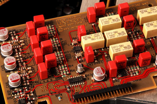
Now, let's start bashing Levinson products 😀
No, Gerhard! FYI it can be done in modern software. I did mine in Accel EDA, the predecessor to P-CAD (now Altium Designer).
Altium did buy P-CAD at some point and kill it, but I think the Altium Designer software itself traces back more clearly to Protel. Maybe one day they will stop adding 5 million features per release and make it more stable.
Do the 9 ps risetime scope
Mine is bigger, 7pS from an 11801C with the 40GHz sampling head. Noisy as hell, though, the 20GHz sampling heads are much better noise wise. 😀.
- Status
- Not open for further replies.
- Home
- Member Areas
- The Lounge
- John Curl's Blowtorch preamplifier part IV