Especially critical is the clock signal --->You may also notice what appear to be “shelves” or “steps” in the clock edges. This is caused by reflections of the clock signal as it travels along a trace ...."
For any DAC I have seen the clock is almost exclusively confined to inside the chip, PC runs have nothing to do with it. As pointed out the Luxman quote was for audio frequency signals and in that context nonsense.
Last edited:
OK Everyone here raise your hand who has worked with precision complex measurements at microwave freqs? Like to know the name here. Must be at primary or secondary standards lab level. Microwave pcb software user also accepted.
One (me) and others?
Its to help with the lack of credibility issue here.
Me, surprised? I have a Wiltron 360B with 3611A test set and two 40GHz sweepers, one is a 6769B digital synthesizer, the other one is an 360SS69 analog synthesizer (need 2 for mixer measurements), all former US Air Force property. Anritsu calibration kit (mechanical and TDR), test cables, 3680K 40GHz microstrip fixture.
I'm ready to bet you have as much clue about microwave design as you have about analog and digital design, that is, asymptotically zero. Sue me.
Last edited:
OK Everyone here raise your hand who has worked with precision complex measurements at microwave freqs? Like to know the name here. Must be at primary or secondary standards lab level. Microwave pcb software user also accepted.
One (me) and others?
Its to help with the lack of credibility issue here.
I took several graduate courses with labs from one of the great microwave designers and personal friend of Skockley at Bell Labs. We measured waveguide losses at 10ths of a dB after computing them from first principles.
Microwaves have nothing to do with this why do you keep insisting?
Last edited:
For any DAC I have seen the clock is almost exclusively confined to inside the chip, PC runs have nothing to do with it. As pointed out the Luxman quote was for audio frequency signals and in that context nonsense.
Hrrm, many/most DAC boards carry an oscillator as a component on the board.
//
Hrrm, many/most DAC boards carry an oscillator as a component on the board.
//
I said almost, an oscillator tied to a pin or two. The critical timing between circuit blocks is generally all on the IC otherwise from simple capacitance/delay issues nothing would work (in some cases).
Have you looked at the motherboard of your computer, or inside your cell phone?I doubt such sophisticated microwave software is being used in many consumer products and their pcb layout.
OK Everyone here raise your hand who has worked with precision complex measurements at microwave freqs? Like to know the name here. Must be at primary or secondary standards lab level. Microwave pcb software user also accepted.
One (me) and others?
Its to help with the lack of credibility issue here.
THx-RNMarsh

I honestly confess that I believed the supplier of my PCB layout program that 45 degrees was better than 90 degrees and that rounded corners were even better, so didn’t give it any further thoughts.
Good to know that it is not the case and although it doesn’t make things worse, I will neglect that advise next time.
Hans
Good to know that it is not the case and although it doesn’t make things worse, I will neglect that advise next time.
Hans
 Tournesol is in the sinbin. Syn08 your provocations resulted in him being there, so you should watch yourself too.
 I suggest everyone starts to think about raising the level of this thread (which has hit an all time low), or you may find that something that has been a part of the furniture on this forum for many years ends up closed and sinking into obscurity.
I'm slowly starting to lose my sense of humor, this topic asymptotically approaches pathology. Almost every audio myth and legend is revived by the same gang of professional BSers, accompanied by the usual gang of diversionists ready to eat crow for a chunk of ego. I thought we stopped at Bybees, but no.
Too bad the credibility of this entire forum is at stake; there's a treasure of good engineering in the archive that not many care to dig for after reading some of the crapola of the day.
FWIW, TI is doing a frac PLL with integrated VCO, up to 18GHz on a single chip, with very sharp corners in multiple metallization layers.
Better not waste time here even with reading. You posting here why?
There may be sharp corners involved but they act as inductors and the Z is carefully controlled and that is accounted for in the software. I doubt such sophisticated microwave software is being used in many consumer products and their pcb layout. Though you CAN use 90 degree corners, clock signal jitter is very critical to audio and best methods should be used even if it is a PITA to get the best performance that is possible with pcb layout.
Most high speed use 45 degree angles or less and never 90 degree. Better is to get there with two 45 degree angles. At least use EAGLE software .. I own it since before they were bought and the price then went way up. But still worth it.
Top 10 Tips for High Speed PCB Design | EAGLE | Blog
THx-RNMarsh
EAGLE is hobbyist grade PCB software. No serious commercial outfit does layout in EAGLE. I fear you really are out of your depth here.
Nobody will go after you directly, so don't worry. All it takes is a letter from offended person's lawyer to the owner of this site (diyaudio) that if they do not take _x.y.z_ measures, they might get sued for libel. No need to prove anything and no smart site owner will ever argue and defend some stupid anonymous troll's freedom of speech rights. Soon after the whole threads will be deleted and all troublemakers banned from the site permanently. I've seen it happen in other places, so carry on.Please, please go ahead, that would be a first in the history of social media! I can't wait to see your damages claim (lost sales, probably) and to watch you going bankrupt from legal costs early during the discovery phase.
For the hard of google, here is the full joy of the luxman PCB layout. I'll be honest it looks like the hand drawn boards I remember as a kid.
For Balance the measurements Luxman DA-06 D/A processor Measurements | Stereophile.com . Nice -90dB undithered sine wave. Choice of filters for those who are happy with something that mathematically must be wrong. Other than slightly higher than expected jitter on the spdif input a fine set of measurements, just not really much better than a $400 DAC.
For Balance the measurements Luxman DA-06 D/A processor Measurements | Stereophile.com . Nice -90dB undithered sine wave. Choice of filters for those who are happy with something that mathematically must be wrong. Other than slightly higher than expected jitter on the spdif input a fine set of measurements, just not really much better than a $400 DAC.
Attachments
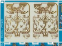
That's off their website for their DA-06, which is current product. These are the analog boards. Digital uses PCM1792A DAC.
For any DAC I have seen the clock is almost exclusively confined to inside the chip, PC runs have nothing to do with it.
True for most ESS implementations. However, ESS dacs can be run in synchronous mode like AKM dacs (and they should be for best sound quality). It means that clock signals do have the be run to the USB interface and possibly to any other signal processing ICs. Just did some work on that here as it happens. Jitter can easily become problem. Had a bad LDO regulator circuit powering a clock buffer chip which resulted in audibly increased clock jitter. Fixed now, but for best sound quality have to watch carefully for any jitter issues. Turns out that is what causes a lot of SD dac reverb tail loss (although not the only cause of it). Now you know.
Regarding corners in pcb traces, for AKM dac clocks running at 22/24MHz I don't worry about it.
Last edited:
Bad as in not working at all as a regulator or is this another 'measurements or it wasn't jitter' case?
BTW you do realise that all the audio rags have been saying async sounds better for the last 10 years? You should correct them.
BTW you do realise that all the audio rags have been saying async sounds better for the last 10 years? You should correct them.
Bad as in not working at all as a regulator or is this another 'measurements or it wasn't jitter' case?
BTW you do realise that all the audio rags have been saying async sounds better for the last 10 years? You should correct them.
To be fair, I think they mean the USB interface working in asynchronous (async isochronous) mode. Whereas Mark is talking about not using an ASRC by feeding the clock back to the USB receiver.
Of course, there are no measurements and these magical reverb tails come up yet again.
BTW you do realise that all the audio rags have been saying async sounds better for the last 10 years? You should correct them.
I said dacs sound best with their own clocking in synchronous mode. It means they use what is called asynchronous USB, which is asynchronous with the PC's internal clocking.
Last edited:
Looks good to me.For the hard of google, here is the full joy of the luxman PCB layout. I'll be honest it looks like the hand drawn boards I remember as a kid.
As JC mentioned a couple of posts down, every small detail may be of importance. If one can do it, why not?
Here's small fragment of mine from about 10 years ago. Plain vanilla low frequency stuff. 🙂
Attachments

- Status
- Not open for further replies.
- Home
- Member Areas
- The Lounge
- John Curl's Blowtorch preamplifier part IV