Hello. I am building a preamplifier. I need to switch in an out a gain stage.
What is the best method for the lowest noise (not the pop), with a single dpdt relay ?
Do I have to ground the input of the 2nd stage ? less noise ?
Does an energized relay is more noisy than a off relay ? is it really noticeable ?
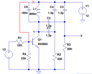
I need to get the best method I have seen a lot of ways but I have not seen this way :
EDIT : I used transistor symbols for lack of proper triode ones 😉
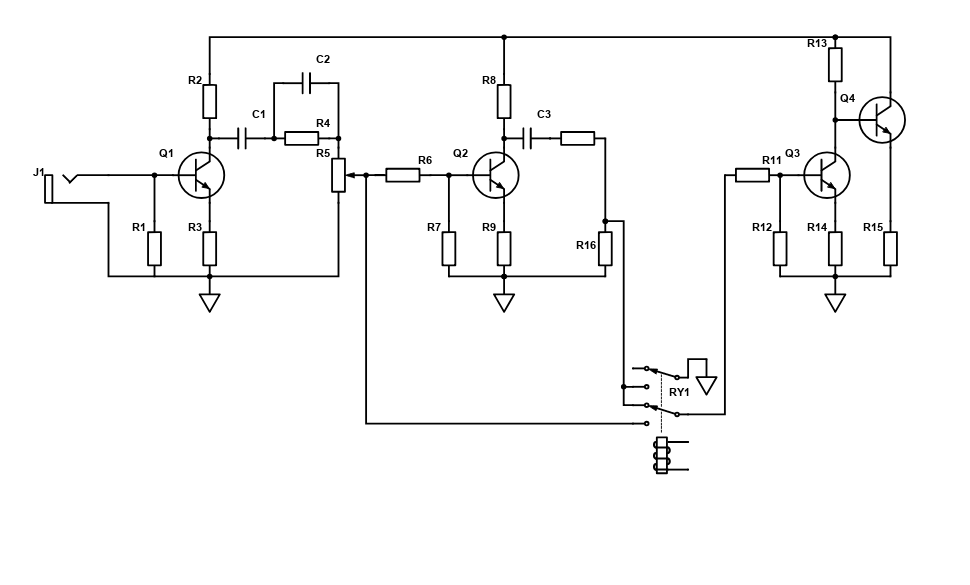
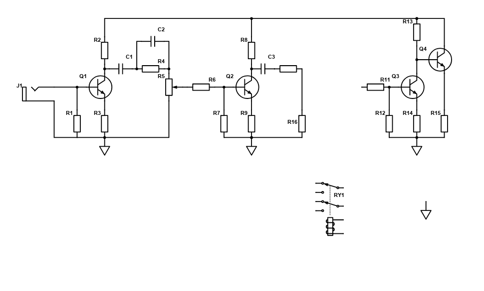
Here is a version without the wires on the relay if you want to draw your version.
Thank you.
Also, I don't know how to embed image I hope it works.
What is the best method for the lowest noise (not the pop), with a single dpdt relay ?
Do I have to ground the input of the 2nd stage ? less noise ?
Does an energized relay is more noisy than a off relay ? is it really noticeable ?
I need to get the best method I have seen a lot of ways but I have not seen this way :
EDIT : I used transistor symbols for lack of proper triode ones 😉
Here is a version without the wires on the relay if you want to draw your version.
Thank you.
Also, I don't know how to embed image I hope it works.
Last edited:
Your drawing looks like it will work well enough, but I see no triodes (just BJTs), and the input being a jack tells me this is for an instrument like a guitar?
Thank you.
Yes I did not have the triode symbol in the free digikey schem-it, and I wanted a quick drawing.
To be fair, I draw an instrument amplifier just because that was in my mind, but in fact it's a microphone preamp that I want to use it in (to add a low gain "coloration stage").
I need the lowest noise possible.
I was wondering if I ground the input of the second stage, will I get less noise ?
I was thinking if you guys know the ultimate way to switch out a stage for the lowest noise (both when the relay is off or on).
This should work provided the "grid" of Q3 is actually at a GND potential.
This depends on the value of R12: if it is large, the voltage won't be exactly zero, and this will cause a small pop during the switching.
Another thing to consider is the capacitive coupling of the relay coil to the contacts. Even with an antiparallel diode, the kick back could still be problematic.
A 100nF cap across the coil should eliminate any potential issue.
If the relay has a grounding pin connected to the metallic parts, using it will also help.
Thank you very much.
My relay is a Panasonic plastic case. No grounded metal part.
I was going to use a diode for the coil (I read it's the best method against kickback but the slowest).
What does the cap accross the coil will provide. I understand it's a snubber but what will it provide over the diode ?
My relay is a Panasonic plastic case. No grounded metal part.
I was going to use a diode for the coil (I read it's the best method against kickback but the slowest).
What does the cap accross the coil will provide. I understand it's a snubber but what will it provide over the diode ?
The diode is still necessary: with only the cap, there will be a largish oscillatory ringing that needs to be clamped.
The capacitor will slow the transients that couple easily, and result in clicks
The capacitor will slow the transients that couple easily, and result in clicks
Do you absolutely have to use a relay? A simple toggle switch would certainly get the job done.
A suggestion I would give regarding the relay is to put the optional stage dead last in the block diagram, then let the relay switch between those two outputs. That would minimize the risk with noise issues, but could be problematic if your last block is intended to act as a buffer.
A suggestion I would give regarding the relay is to put the optional stage dead last in the block diagram, then let the relay switch between those two outputs. That would minimize the risk with noise issues, but could be problematic if your last block is intended to act as a buffer.
Bring the signal to the front panel and back again would need attention to shielding, might compromise the low noise requirement if not done carefully.Do you absolutely have to use a relay? A simple toggle switch would certainly get the job done.
Thank you all.
Elvee. If I understand correctly, the diode will make a path back to the psu, for the stored energy, when the coil when de-energized.
The stored energy oscillate, so the capacitor dampen the ringing to a lower frequency that will not couple at lower capacitance. Right ?
audiowize. I need a relay because I might need to switch 2 thing at the same time.
But I will use a switch if I don't need a relay.
You know I will definitely have to use a relay in other projects at one point or another, so your knowledge will be very valuable 🙂
Thank you Mister Blencowe. I will read it and answer back when I finish digesting everything.
I was wondering about the noise in general, not only the click and pops ;
like will I have more circuit noise if I ground the INPUT of the stage vs. the output of the stage.
Or if I should ground both the in and out. So your book pages are a godsend, I will read them carefully.
Oh, I did not think about that. Thank you.Bring the signal to the front panel and back again would need attention to shielding, might compromise the low noise requirement if not done carefully.
Last edited:
Thank you all.
Elvee. If I understand correctly, the diode will make a path back to the psu, for the stored energy, when the coil when de-energized.
The stored energy oscillate, so the capacitor dampen the ringing to a lower frequency that will not couple at lower capacitance. Right ?
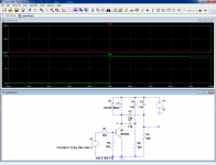
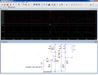
Here is a sim based on a real example: a Fujitsu D012/02CT (DPDT, 12V 300Ω).
Parasitic parameters have been measured and reproduced.
First, the regular configuration, using a // diode (1 is the coil, 2 one of the contacts):
The coil node is clean, but a spike of almost 4V appears on the contacts.
With a parallel cap, a large oscillatory ringing is visible on the coil, but the fed-through spike is much lower in amplitude, and less harsh:
When both the diode and cap are in service, the waveforms are clean, and the feedthrough spike is limited to 10mV:
Attachments

Wow I am so grateful to you Elvee.
It's clear I understand now, thank you for taking the time.
I really need to learn LTspice...
Ketje. I am not advanced enough to understand. Sorry.
Hi jan.didden. Why is it not healty ? In the Merlin Blencowe book it is used.
Is it because it add noise to the ground ? Or loading (power waste ?)
It's clear I understand now, thank you for taking the time.
I really need to learn LTspice...
Ketje. I am not advanced enough to understand. Sorry.
Hi jan.didden. Why is it not healty ? In the Merlin Blencowe book it is used.
Is it because it add noise to the ground ? Or loading (power waste ?)
Be aware that the solution I proposed addresses only a small part of the problem: you want to use a relay, and I just helped you to eliminate one potential issue related to it, but pops and clicks have many different origins and without synchronous or soft switching (both impossible without electronic control), some random events will remain.
Note that if you use a discrete transistor relay driver, Ketje's solution will provide the ultimate transition control
Note that if you use a discrete transistor relay driver, Ketje's solution will provide the ultimate transition control
Hi. I know that clicks and pops are related to different potential on the contacts. I also know there is contact bounce on relays. As for soft switching, I will try to read about this subject.
Thank you Ketje.
Ketje solution I will definitely try to understand, because it did not do anything on ltspice when I clic simulate.
edited .. Ketje, You put the return path through the transitor instead of the diode ! that it ?
Thank you Ketje.
Ketje solution I will definitely try to understand, because it did not do anything on ltspice when I clic simulate.
edited .. Ketje, You put the return path through the transitor instead of the diode ! that it ?
Last edited:
Every change on the collector side is passed to the base (via the C) resulting in a reverse reaction by the transistor.edited .. Ketje, You put the return path through the transitor instead of the diode ! that it ?
The collector voltage (and current) cannot make jumps but has to change gradualy, following the charging/decharging of the capacitor.
It's a (simple) current integrator.
Mona
Ah I understand it ramp to 12v, also no spike gets coupled. Thank you.
Jan.didden, you were right no need to ground the output, unless you have 2 channel on the same path and want to mute one 😉
Jan.didden, you were right no need to ground the output, unless you have 2 channel on the same path and want to mute one 😉
Your original circuit will basically work fine.
No need to mute the unused triode when not in use, we are not talking monster gain or hard clipping stages here which might generate strong wild harmonics which can be coupled through parasitic capacitances, poor grounding or filtering, but a mild Mic preamp.
That said, be careful with grounding and layout, follow usual good practices.
Beware that adding an extra gain stage will very probably create annoying acoustic feedback; if your objective is adding extra tube flavouring, you might consider attenuating second triode output so switching it IN/OUT circuit does not vary total gain, simply adding its own desirable quirks.
A minor point: you should add the warning label "I used transistor symbols for lack of proper triode ones" to your drawings 🙂
Thank you.
So no need to disconnect the input of the second triode or ground the output, it will not lead to less noise, but in high gain (say higain overdriven) it will be beneficial ?
Also for grounding it's my third build, and at first I tried a lot of way, star grounding was noisy (probably not done right), now I use a bus grounded at the input of the chassis, and I had good luck with this method if you respect a certain order of the signal.
Do you have a preferred grounding method ?
Ah thank you. I was planning to add a divider after the 2nd triode, but not at the input I will test both ways with pots.Beware that adding an extra gain stage will very probably create annoying acoustic feedback; if your objective is adding extra tube flavouring, you might consider attenuating second triode output so switching it IN/OUT circuit does not vary total gain, simply adding its own desirable quirks.
- Home
- Amplifiers
- Tubes / Valves
- Switch a triode in circuit