I see that Jim's boards on ebay are cheap and look very nice but for those set up for toner
transfer it is still a nice option.
transfer it is still a nice option.
This is what I accumulated a while ago, it all is in the public domain.
Attachments
Heard he retired, think health issues.
i had several email exchanges with him, don't know how he is today...
Member
Joined 2009
Paid Member
What's the purpose of the bootstrap in the LTP? I've never seen that before....
It increases the effective impedance of the collector load which increases voltage gain for a higher feedback factor.
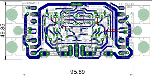
This is a high gain-bandwidth amp with fast MOSFETs so great care is required with pcb layout and all chassis wiring to avoid parasitic oscillations. I made my own version, “TGM7”, with some improvements but it took a couple of attempts to make it robust. The end result is, I believe, far better layout than the original but it was a learning experience.
Last edited:
Thanks, Bigun.
Let me play this back to make sure I'm understanding it.
To increase gain in an LTP you increase the collector resistance. However, the rail voltage drops proportionally over this resistance, so at some point you run out of voltage and start to clip the input signal.
The bootstrap communicates the AC signal to the point between the two resistors, so you've got a bit more voltage when you need it (and a bit less when you don't).
Do I have that right?
Cheers,
Jeff.
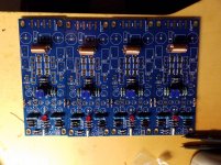
Of course we are !!😀My nice mail man brought these four pcb today, I got a little work done on them, I will post some thoughts and measurements when done, if anyone is interested.
Member
Joined 2009
Paid Member
Thanks, Bigun.
Let me play this back to make sure I'm understanding it.
To increase gain in an LTP you increase the collector resistance. However, the rail voltage drops proportionally over this resistance, so at some point you run out of voltage and start to clip the input signal.
The bootstrap communicates the AC signal to the point between the two resistors, so you've got a bit more voltage when you need it (and a bit less when you don't).
Do I have that right?
Cheers,
Jeff.
Nothing wrong with your description. Another way to look at it is that the AC signal to the point between the two resistors means that the lower resistor has the same AC signal at it's top and at it's bottom. With a constant voltage across it, the current will be close to constant. Hence it behaves like a constant current source which is effectively a very high resistance. With a high effective resistance in the collector you get a higher voltage gain and hence higher negative feedback factor. I think this is a very innovative feature of the design which I credit to Greg Ball.
Member
Joined 2009
Paid Member
In my opinion, you are free to experiment using your ears. Some builders have been known to operate the amplifier in Class A bias. I don't remember clearly but I don't think anybody found this to be of much benefit compared with Class AB.
Because these are FETs at the output they don't have their best performance at the traditional 26mV across the emitter resistors that we see in the classic RCA type amplifier. And usually FETs do better as the bias increases, more or less without limit until it blows up.
I like to run my clone [ TGM7 - an amplifier based on Greg Ball SKA ] at a bias that keeps the heatsink at a pleasant warm temperature which ended up at around 70mA per output pair or somewhere around 150mA per power rail total for each channel.
Last edited:
Thanks for your reply bigun.
Yes I saw many opinions regarding setting bias, and I tried with 150 ma per device, couldn't really hear any difference, and heatsink got more hot than good, also when I start it up cold with this high bias setting it draws alot of current in 5 minutes before it stabilizes, I will aim for lower bias and longer lifespan.
I live in north maybe have a flip switch with summer/winter bias 🙂.
Thanks again.
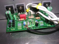
Thread bump! I ordered a set of Jim's boards. I have recently completed a honey badger build, and am ready to tackle the next project. I chose this amp because of the compact layout, and the high power output. I am using large 3 way speakers that like lots of power. The compact layout and relatively high voltage rails capability will let me take advantage of some parts I have laying around from a dead Yamaha home theater receiver. I plan on reusing the case, the heatsinks, and transformer. The heatsinks are compact, and are setup to have a fan pushing air through them, as can be seen in the pic.
Can I use a single power supply with these, and run a total of 40kuf? Was planning on using a standard crc type supply with a bridge rectifier. Rails should be about +-56v.
Can I use a single power supply with these, and run a total of 40kuf? Was planning on using a standard crc type supply with a bridge rectifier. Rails should be about +-56v.
Attachments

- Home
- Amplifiers
- Solid State
- SKA GB150D now public domain...