FIXED: Yamaha RX-700: loud pop from the left speaker during shutdown
Hello all,
I have Yamaha RX-700 amplifier from the eighties. The device has a common "soft start / shutdown system" that should prevent pops from the speakers during startup and shutdown. For an unknown reason this feature is not working properly anymore during shutdown: when the relay cuts power from the speakers, a loud pop (or more like a bang) is heard from the left speaker (and left headphone speaker). Turning volume knob to zero before shutdown does not help.
I called to a repair guy but he was not even interested to look the device because he claims there's too many possible causes to this phenomenom so it would probably be costly and therefore not recommended.
I'm quite a noob in electronics so I have no clue what to do. Nonetheless I measured the left channel speaker output terminal several times with multimeter and got something like +2V spike. However, my meter resolution is only 3 samples per second so I probably didn't get max value.
I also measured some voltages from the PCB and noticed that just when the relay cuts power from the speakers, the voltage jumps suddenly from 0 to 52-53 volts on both channels and then starts to fade back to 0V. Is this normal?
I also tried to measure the power supply voltages. From the middle pin I got 65 VAC although this goes directly to the "ground" or "neutral" collector on the PCB. Is this normal? Other pins give me 90VAC and 40VAC.
If I shutdown the device from the main power switch, there's no bang from the speaker even though the shutdown sequence should be the same: first the power-switch-relay cuts power from the protection circuit, then the speaker relay cuts power from the speakers. Or that is what I think is happening.
The simplest fix to this issue would be to press the "speaker select button" to deactivate the speakers and then shutdown the device but I don't like that.
Any ideas what to do?
Last edited:
No Service Manual or circuit found in usual libraries...
Your measurements were ok sofar, but not enough yet to pinpoint the cause.
Better find another engineer or have a thourough visual inspection if you can spot corroded pins, leads or solderings, or capacitors (firm cylinder-shape components) with 'swollen' appearance. Post pictures if suspicious candidates are emerging.
Yeah, would be handy to have a schematic. The sudden jump from 0 to 50+V at power
down might suggest that the negative rail has immediately "disappeared". Long shot
would be to check the main filter cap for the negative rail, maybe post some pix. Also
helpfut to monitor the negative rail, at the cap is fine, at power down.
down might suggest that the negative rail has immediately "disappeared". Long shot
would be to check the main filter cap for the negative rail, maybe post some pix. Also
helpfut to monitor the negative rail, at the cap is fine, at power down.
Thanks for the replies so far.
I downloaded the service manual from RX-700 Radio Yamaha Co.; Hamamatsu, build 1987/1988, 1 pictu but unsure if it's ethical to post it here. Images 2, 3 and 4 (image 4 perhaps being the most valuable piece of information) show the tone amp, power amp, protection, power supply and voltage regulator schematics.
I already re-soldered one transistor (Q137) which had loose contact and caused the display malfunction. There is also some green transparent liquid stuff under one transistor (Q133 in power supply / voltage regulator section) but I guess it may have been there from the beginning. Otherwise I have not find anything suspicious from the PCB.
Is the "main filter cap for the negative rail" perhaps a big green 100uF/63V capacitor that is between tone amp and power amp? I measured -55V from it when the device is on and no spikes during shutdown. Voltage steadily decreases to 0V in few minutes.
Main filter caps(8200uf/63V) will be the largest caps you can see.
C256 is for the negative rail.
C256 is for the negative rail.
Negative side de-charges to -5 volts in 2min 55s. Max voltage -56.Main filter caps(8200uf/63V) will be the largest caps you can see.
C256 is for the negative rail.
Positive side de-charges to 5 volts in 1min 0s. Max voltage 56.
I'm wondering if it's safe (to the device) or usefull at all to put red probe to the speaker relay's left channel input and black probe to the ground and measure current during shutdown when volume is at minimum?
Assuming you meant voltage rather than current, that's what I would suggest doing.I'm wondering if it's safe (to the device) or usefull at all to put red probe to the speaker relay's left channel input and black probe to the ground and measure current during shutdown when volume is at minimum?
Perhaps you will already find a substantial DC offset before shutdown, in which case you would have to investigate:
* whether it is equally present at the feedback side of the input LTP
* whether it is also present on the input side
* whether it depends on volume pot setting at all.
I would not be surprised if the issue turned out to be simply the electrolytic cap in the feedback ground leg leaky or shorted (look for a 47-220µ/6.3 V near the input; there's also another 1µ/50V in an input bootstrap but that's more likely to be dried out than leaky), or a bad solder joint at one of the input LTP transistors.
I did find a service manual for the RX-500 on HFE, that should at least give us an idea what we're dealing with. Should the input pair be A970 (2SA970) instead of C2240 (2SC2240), perhaps consult AX-400 instead.
Thank you all for your help and ideas.
I managed to fix the problem temporarily with the help of forum member "MarsBravo" who suggested testing the speaker relay after giving him some measurements from the board. When I cleaned the relay contacts, the shutdown sequence stopped causing bangs. However, it lasted only 20-30 starts & shutdowns as the device is making pops again, this time even on startup. Not as loud though as before, at least not yet. I have to replace the relay and hope the problem goes away permanently.
I'm still curious why a relay can cause something like this. Almost like the contacts would be stuck to each other causing the relay to be way too slow. Also, amps often cause "pops" during shutdown & startup but I have never heard any amp doing "pops" this loud. Therefore, I fear that the circuit is malfunctioning which causes the relay to fail prematurely.
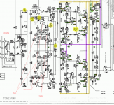
In case someone would have alternative theories, here's the schematics of the amp section. Measured values are marked green when the device is on and yellow during shut down. Yellow values are not very accurate because my multimeter sampling rate is not very high.
I managed to fix the problem temporarily with the help of forum member "MarsBravo" who suggested testing the speaker relay after giving him some measurements from the board. When I cleaned the relay contacts, the shutdown sequence stopped causing bangs. However, it lasted only 20-30 starts & shutdowns as the device is making pops again, this time even on startup. Not as loud though as before, at least not yet. I have to replace the relay and hope the problem goes away permanently.
I'm still curious why a relay can cause something like this. Almost like the contacts would be stuck to each other causing the relay to be way too slow. Also, amps often cause "pops" during shutdown & startup but I have never heard any amp doing "pops" this loud. Therefore, I fear that the circuit is malfunctioning which causes the relay to fail prematurely.
In case someone would have alternative theories, here's the schematics of the amp section. Measured values are marked green when the device is on and yellow during shut down. Yellow values are not very accurate because my multimeter sampling rate is not very high.
Attachments
Last edited:
My prime suspects would be C207 and C211. 47µ/6.3 V caps that have never seen much DC for 30+ years are not unlikely to be seriously leaky and could cause enough DC offset for the jump in output voltage to be clearly heard when the relay engages.
You could try reforming them with the help of a DC power supply (maybe 7-12 V) and a high-value resistor (maybe 1 megohm) to apply a charge at correct polarity, though in practice nobody does that as success may very much vary. A pair of new high-quality 100 µF capacitors connected back-to-back would be a good and hopefully long-term-stable replacement. Hard to go wrong with genuine Nichicon or Panasonic or other Japanese manufacturers (e.g. the trusty Panasonic FC series). Obtain from a major electronics distributor, not some dodgy eBay seller.
This is not the only possibility though. There is also a muting circuit on the input side. You could have DC at pot wiper level (where from though? there isn't much after C195 at all, could almost only be leakage though Q113), which would be pulled down by Q113 as it engages, or Q113 might actually not be doing anything when it actually should. These muting transistors do fail. Compare voltages with Q114 and consider removing Q113 for testing purposes.
This case would be one of those where having an oscilloscope would be super handy.
Thanks for the tips! I have a pile of old computers and soundcards, I believe I could build a home made oscilloscope from them and make more accurate measurements! But it will happen in round two in the future, because I already put the parts together in a belief the device is working again. Now I need to take a small break from this.My prime suspects would be C207 and C211. 47µ/6.3 V caps that have never seen much DC for 30+ years are not unlikely to be seriously leaky and could cause enough DC offset for the jump in output voltage to be clearly heard when the relay engages.
You could try reforming them with the help of a DC power supply (maybe 7-12 V) and a high-value resistor (maybe 1 megohm) to apply a charge at correct polarity, though in practice nobody does that as success may very much vary. A pair of new high-quality 100 µF capacitors connected back-to-back would be a good and hopefully long-term-stable replacement. Hard to go wrong with genuine Nichicon or Panasonic or other Japanese manufacturers (e.g. the trusty Panasonic FC series). Obtain from a major electronics distributor, not some dodgy eBay seller.
This is not the only possibility though. There is also a muting circuit on the input side. You could have DC at pot wiper level (where from though? there isn't much after C195 at all, could almost only be leakage though Q113), which would be pulled down by Q113 as it engages, or Q113 might actually not be doing anything when it actually should. These muting transistors do fail. Compare voltages with Q114 and consider removing Q113 for testing purposes.
This case would be one of those where having an oscilloscope would be super handy.
I'm in the process of hunting a new relay and some other parts for other projects, I guess I should also buy a few caps just in case. But I don't know what I should be looking for. 47uF/6.3V and 100uF/6.3V caps seems to be quite rare in electrolytic format. I'm also wondering, should the cap be low-ESR and what does "BL" mean, like "47uF/6.3V BL"? Is it shorthand for "barrier layer"? Those seems to be very rare too?!
Take a look at what size and pin pitch the originals are. If you can fit a 10 V rated part instead, fine.
I couldn't find much on this "BL" either, it doesn't seem to be a Nichicon series in any case - are they blue-colored caps by any chance? In any case some others are marked "MUSE", which I assume indicates Nichicon Muse caps, so "BL" probably denotes a series as well - whatever their standard type was, apparently. Maybe you can find one with the manufacturer and series clearly visible on the jacket, I pretty much assume it would be a general purpose one from back in the day.
I couldn't find much on this "BL" either, it doesn't seem to be a Nichicon series in any case - are they blue-colored caps by any chance? In any case some others are marked "MUSE", which I assume indicates Nichicon Muse caps, so "BL" probably denotes a series as well - whatever their standard type was, apparently. Maybe you can find one with the manufacturer and series clearly visible on the jacket, I pretty much assume it would be a general purpose one from back in the day.
Thx. These BL caps are not blue but black, with light brown or golden-brownish markings. I will open the device someday to get closer look.Take a look at what size and pin pitch the originals are. If you can fit a 10 V rated part instead, fine.
I couldn't find much on this "BL" either, it doesn't seem to be a Nichicon series in any case - are they blue-colored caps by any chance? In any case some others are marked "MUSE", which I assume indicates Nichicon Muse caps, so "BL" probably denotes a series as well - whatever their standard type was, apparently. Maybe you can find one with the manufacturer and series clearly visible on the jacket, I pretty much assume it would be a general purpose one from back in the day.
If you amplifier play music ok then your problem may be mainly caused by the speaker protection circuit or relay.
If turn on "pops" happened then the relay failure maybe the case.
If turn on "pops" happened then the relay failure maybe the case.
- Home
- Amplifiers
- Solid State
- Yamaha RX-700: loud pop from the left speaker during shutdown