Why do more research? Just time align them and be done with it.
Maybe so. If the DSP and the dac are good enough.
Missed the test setup discussion. I was probably looking for the big block diagrams and bold caps that makes sense to me...-Test accuracy and repeatability requirements for inductive measure of the effect corrosion can have on inductance vs frequency measurements.
-A test setup to ascertain possible noise and distortion effects for a wire pair with corrosion interstrand, again with level of effect calculations..
The takeaway is...."he talked about zip cord, which nobody uses anymore"
Sigh...
jn
I know, we are a tough audience. The average sub 5 sproglet is still worse 😛
I know, we are a tough audience. The average sub 5 sproglet is still worse 😛
Sproglet??? I have never heard that before...understand it, just never heard it..😀
That said, you owe all sub 5 sproglets an apology...😉
jn
Richard, thanks for the schematic.
I can certainly see the benefit to driving the externals with the audio, as they would tend to be major dust collectors with a constant bias.
Are ESL's designed for normal maintenence, like dusting the inner film? I assume you wouldn't want to wait until little snaps occur, as I could see pinholing as an issue.
jn
A very interesting power supply for RNM's electrostatic loudspeaker.
As I read it, a line voltage step up transformer drives a resistor bridge where there are two voltage dependent resistors driving a voltage multiplier stage that delivers the final voltage through a capacitor protected neon lamp. This voltage is marked as I read it to vary from 5 to 25 kilovolts.
The audio is fed through two step up transformers in a balanced configuration to membranes that are on each side of the high voltage charged panel. Across the input to the transformers there is a clipper circuit that with a bit of a low pass filter is set to limit the input to the transformer to 30 volts peak or so.
There is a 555 circuit which I suspect is an audio turn on delay.
It appears there is not very good regulation on the high voltage supply. Seems to me the stiffness of the membranes would be quite dependent on the actual high voltage level as at DC they are effectively grounded.
As much as it pains me to ever think JN might be right about something.... 🙂
Last edited:
That said, you owe all sub 5 sproglets an apology...😉
jn
I have a (nearly 3) year old at home that proves my point. We named her Vidya for the goddess of wisdom. Actually should have been Kali. Daily she reminds me of the scene from Jurassic park that ends 'clever girl'. She will go far and leave a trail of destruction behind her. I'm so proud that the hybridisation program seems to have worked...
I'm not sure whether to say "my work here is done" or "I hate your guts"😀It appears there is not very good regulation on the high voltage supply. Seems to me the stiffness of the membranes would be quite dependent on the actual high voltage level as at DC they are effectively grounded.
As much as it pains me to ever think JN might be right about something.... 🙂
Actually have been having success with the 1-72 tapping of aluminum. Did make a tap block to support the tap vertically, and actually tap directly on the mill immediately after drilling the #53 bit hole. The four jaw comes in today, I can't wait..tools, must have more tools..
Oh, btw. Now looking for a pin vice that can hold these taps, the tap tool with handle is way overkill, I just spin the knurled part between thumb and forefinger..
jn
Last edited:
We are drifting away from the question: has the applied AC Mains voltage effect on the HF roll off frequency of the ESL speaker ?As I said, the resultant force on the membrane will be altered by the hv supply level, so that was what I was talking about.
This discussion is almost exactly the same as an electrodynamic where the magnet strength is varied by changing the coil current.
jn
Be aware that the membrane of an ESL is driven with opposite signals from two sides.
The same current sourced from one side is sunk on the other side.
This is a push-pull topology where the audio signal does not charge/discharge the membrane.
The force on the membrane will be altered when HV changes, giving the ESL a different gain, but that applies to all frequencies and not just HF.
However there is some regulation in the HV voltage to compensate for changing AC voltages.
Compare the charge on the membrane to the magnetic field strength working on a voice coil.
Increasing this field strength with stronger magnets does alter the gain but not increase the FR of an electrodynamic speaker.
Hans
I can confirm that XP is 18 AWG (counting strands on this stuff is no picnic). The appearance was tuned to look "Monstrous". Be sure you are not confusing XP with OMC which is closer to 12 AWG but looks similar. Its pretty academic since Monster is pretty much out of the cable business (and be really cautious of the Monster from Walmart).
Yah, it says XP on it anyway......I’ll take your word for it but they sure did a good job making it monstrous!
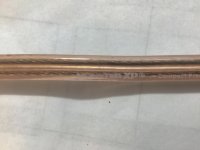
Kindly weird the way it corroded like a candy cane.
Attachments
We are not drifting, that is the crux.We are drifting away from the question: has the applied AC Mains voltage effect on the HF roll off frequency of the ESL speaker ?
Yes, that is clear from the schematic. It works exactly the same with either the plates or the membrane pushed by the audio.Be aware that the membrane of an ESL is driven with opposite signals from two sides.
The same current sourced from one side is sunk on the other side.
This is a push-pull topology where the audio signal does not charge/discharge the membrane.
Again, as I pointed out earlier, the system phase and amplitude response of the physical systems I work with are altered by the drive force as well as the resistance to that drive force. That is why I mention it in regard to an electric field driven system.The force on the membrane will be altered when HV changes, giving the ESL a different gain, but that applies to all frequencies and not just HF.
The schematic Richard posted does not appear to be regulated.However there is some regulation in the HV voltage to compensate for changing AC voltages.
I do wonder why the hv goes to the film via a neon bulb, it would seem that anytime the bulb exceeded threshold it should ionize and produce a click. Maybe that cap across it prevents that. Also, neons are light sensitive, I wonder if it's shielded from light?
jn
Anecdotes again. We have measurements of a bybee and not sure any mechanism besides a small DC resistance is found. So either the science that found the higgs boson is wrong or people are hearing things that are not there...One example is that Bybee devices can and do affect sound, at least in some cases. From what I am told by people I trust, usually they make a good system sound slightly worse, but they can make a not so good system sound slightly better.
Almost impossible given the data set. First thing it would spew out is that silver cable sounds 'bright' and go downhill from there. If we could adopt a tonewheel approach to reporting on what we hear there would be something, but whilst we are using the blunt tools of uncalibrated language you are panning for gold in a place where there is none. All IMO.None the less, I think there is probably some real data about audibility in anecdotal reports, the big problem that I don't know how to overcome is how to extract useful information from it.
Anecdotes again. We have measurements of a bybee and not sure any mechanism besides a small DC resistance is found. So either the science that found the higgs boson is wrong or people are hearing things that are not there...
I didn't say stationary distortion. It may look like noise on an FFT, but sound like distortion. For example, quantizing noise sounds like distortion more than it sounds like noise, at least is does to me.
Also, I agree with Paul Frindle and Jakob on listening reports from trusted listeners (and of course we all know other people disagree with those views).
Last edited:
Also, I agree with Paul Frindle and Jakob on listening reports from trusted listeners (and of course we all know other people disagree with those views).
So is everyone on every forum who reports that they glommed in an expensive capacitor and it sounded better suddenly trusted? I wouldn't trust any of them.
Mark a serious question, do you trust the listening reports of someone who listens habitually at such a high level that their tensor tympani contracts?
So is everyone on every forum who reports that they glommed in an expensive capacitor and it sounded better suddenly trusted? I wouldn't trust any of them.
You might have missed it, but therefore I wrote that the audio field is no exception within our human life. I guess when doing considerations in other parts of your life, there are people whose thought/opinions/recommendations you trust.
If the people who you trust contradict the thoughts of people who you do not trust, do you then conclude - as the range includes everything - that it is all worthless?
Or could it still be that you value some thoughts higher than others?
I seriously don't know if the "community overall" agrees that "silver cable sound bright" - although I certainly know people who think so - but within the group of people whose thinking I value high, that surely isn't the agreed consensus.
Again, the audio field is no exception; picking some extremes might sometimes help to illustrates certain points but that's it; there is no poll that estimates the average opinion on "bright silver cable sound" with good precision, is it? 🙂
Last edited:
W
The force on the membrane will be altered when HV changes, giving the ESL a different gain, but that applies to all frequencies and not just HF.
Hans
That's my understanding too. Peter Walker ( for an unbaffed diaphragm ) derived
P = (Isignal * Vpol)/2picrd, r measuring distance, d plate spacing.
My guess is that change HV might be at most secondary effect on HF.
/örjan
Last edited:
I already told you multiple times that there are many out there. Audio Asylum forum is a prime example which by the official forum rule DBT is not allowed to be brought up. As you have said,The question I ask myself is: is there another forum where we could talk about audio in a friendly atmosphere and share technical works as well as listening impressions, practical tips etc. without having to be insulted permanently by a band of aggressive "fanatics" witch hunts what they imagine are witches with a knife between their teeths and drooling lips, under the blessing of the ... local authorities ?
Oh, yes, please move on !
Then I must have missed your vision on a possible relation AC Mains and HF roll off.We are not drifting, that is the crux.
VDR1 and VDR2 do the “some regulation” that I mentioned.The schematic Richard posted does not appear to be regulated.
The neon bulb provides the charge current but limits the current when one of the panels becomes short cicuited.I do wonder why the hv goes to the film via a neon bulb, it would seem that anytime the bulb exceeded threshold it should ionize and produce a click. Maybe that cap across it prevents that. Also, neons are light sensitive, I wonder if it's shielded from light?
Hans
- Status
- Not open for further replies.
- Home
- Member Areas
- The Lounge
- John Curl's Blowtorch preamplifier part IV