I was about to make the famous Rod Elliott's project 97 to drive a TDA7379 (that I'm yet to do) when I remembered I made a headphones amplifier years ago (it was never used apart from me checking it worked) by joining 2 different schematics for different uses, so I thought: could I turn that one into a preamplifier? What should I modify?
1-Do you think changing the output components values into the ones that P97 have is enough (6r8 to 100r, 220uF to 10uF and 10k to 100k)?
2-Should I remove that 1uF between the inverting input opamp and the Baxandall tone?
3-What about input components, should I modify those?
4-The headphones amplifier was made to use a single 9v PS, do you think it's possible to modify it to use a dual supply? Or it isn't necessary (I think it isn't)?
Or should I leave it as it is?
Or for some other reason it isn't suitable?
Or should I just make the P97 and stop bothering!? 😀
Here are the schematics:
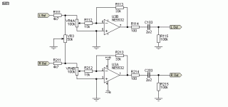
The weird headphones amp:
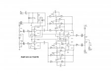
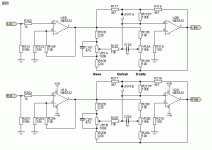
The P97 just in case:
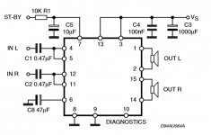
The TDA7379 shcematic from the datasheet (don't know yet what to modify ) :
1-Do you think changing the output components values into the ones that P97 have is enough (6r8 to 100r, 220uF to 10uF and 10k to 100k)?
2-Should I remove that 1uF between the inverting input opamp and the Baxandall tone?
3-What about input components, should I modify those?
4-The headphones amplifier was made to use a single 9v PS, do you think it's possible to modify it to use a dual supply? Or it isn't necessary (I think it isn't)?
Or should I leave it as it is?
Or for some other reason it isn't suitable?
Or should I just make the P97 and stop bothering!? 😀
Here are the schematics:
The weird headphones amp:


The P97 just in case:


The TDA7379 shcematic from the datasheet (don't know yet what to modify ) :

Last edited:
Should work okay as it is. You could use smaller output capacitors to speed up the settling time of the outputs.
You might consider a higher supply voltage which will improve the performance - in testing I've done, NE5532s perform at their best with +-15v rails, they aren't as fast at 9v and you will find there is more distortion - still most likely inaudible, mind you.
You might consider a higher supply voltage which will improve the performance - in testing I've done, NE5532s perform at their best with +-15v rails, they aren't as fast at 9v and you will find there is more distortion - still most likely inaudible, mind you.
Should work okay as it is. You could use smaller output capacitors to speed up the settling time of the outputs.
You might consider a higher supply voltage which will improve the performance - in testing I've done, NE5532s perform at their best with +-15v rails, they aren't as fast at 9v and you will find there is more distortion - still most likely inaudible, mind you.
Isn't the 6,8 Ohms resistor too small anyway?
I'm going to feed the TDA7379 amp with a notebook universal charger. Yes. ..well....I will try at least and see what happens, as I can't find any guide for dummies on how to remove the supposed noise (for example I saw many times "use coils", but never any specs, any formula, type, size of the core, diameter of the wire, nothing). Well the thing is I that will use 15 or 18v for the amp, do you think, as you suggest using more than 9v, I could use that also for the preamp, or sharing that PS will be trouble? Any tips on how to isolate the amp PS section form the preamp PS section to avoid those possible problems?
Better to keep them separate.
Yes better increase the output resistors to say, 1k, if the preamp will be in a separate enclosure ie. any length of cable needs driven
Yes better increase the output resistors to say, 1k, if the preamp will be in a separate enclosure ie. any length of cable needs driven
The tone control bias current flows through the wiper contact to the bipolar opamp input.
This is a recipe for extreme noise spikes when there is intermittency on the wiper/track interface, as the feedback is intermittently lost.
Either use a FET input opamp (which has enough capacitance/bias current ratio), or add caps to every wiper and provide separate DC path for bias currents.
This is a recipe for extreme noise spikes when there is intermittency on the wiper/track interface, as the feedback is intermittently lost.
Either use a FET input opamp (which has enough capacitance/bias current ratio), or add caps to every wiper and provide separate DC path for bias currents.
The tone control bias current flows through the wiper contact to the bipolar opamp input.
This is a recipe for extreme noise spikes when there is intermittency on the wiper/track interface, as the feedback is intermittently lost.
Either use a FET input opamp (which has enough capacitance/bias current ratio), or add caps to every wiper and provide separate DC path for bias currents.
I don't think I will be able to get anything better than TL071/72/74 🙁 Given that the circuit is already done the alternative seems impossible, right?
But are you saying this is a possible problem with the particular design or with all similar designs with bipolar opamps? What about the P97?
By the way, according to the datasheet, the TDA7379 has a typical input impedance of 15 KOhms and a minimun of 10KOhms in bridge mode.
In the P97's page says "Output impedance is 100 ohms, and using the suggested 2.2µF polyester cap, the preamp will drive a 22k load...[...] A polarised electro can be used and polarity is unimportant because there's only a few mV of DC at worst. I suggest a 10µF cap if you use an electro.(which is why I said 10u instead of 2u2)"
In the P97's page says "Output impedance is 100 ohms, and using the suggested 2.2µF polyester cap, the preamp will drive a 22k load...[...] A polarised electro can be used and polarity is unimportant because there's only a few mV of DC at worst. I suggest a 10µF cap if you use an electro.(which is why I said 10u instead of 2u2)"
Better to keep them separate.
Now I realize I don't know exactly how. I read that one of the big problems is grounding, but how do I keep them separated or controled if they will be connected when connecting the preamp to the amp?
Best use an extra power supply (wall wart) for the preadphone amp if feasible... it's not a very power-hungry circuit anyway, so 15 V= / 300-500 mA should be plenty.
Otherwise you would have to make a detailed plan of grounding for the whole pre + power amp. Implementing star grounding with a common power supply is possible but requires that either - or ideally both - preamp and power amp boards do not just blindly join audio ground and power ground, or input and output ground for that matter. You need some options.
Re: mods to the headphone amp, I would replace those 10k pull-down resistors at the output with a 2.5k-10k log (or "fake log") volume pot + a resistor of about 10% the pot value in series with its ground connection. This will give you a ca. 20 dB output level trim, so you can always get output noise down to where it's no longer bothersome. The thing is a bit noisy as-is.
Thinking about it, I'd rather move the pot (as described) to the power amp input. It's the same electrically but any interconnect will see the low preamp output impedance. Speaking of which, replacing its 6.8 ohm resistors by 47-100 ohms is probably a good idea - still plenty low but enough to isolate the 5532 from any undue capacitive loading. (TL07x may need as much as 470 ohms.)
Otherwise you would have to make a detailed plan of grounding for the whole pre + power amp. Implementing star grounding with a common power supply is possible but requires that either - or ideally both - preamp and power amp boards do not just blindly join audio ground and power ground, or input and output ground for that matter. You need some options.
I will use two power supplies (hoping the notebook charger will not give me problems with the amp, I will use a 2000uF 35v, 100nF, some other similar, and probably a 1000uF caps to smooth a bit at least), but in the end they will have to join grounds, right?
Re: mods to the headphone amp, I would replace those 10k pull-down resistors at the output with a 2.5k-10k log (or "fake log") volume pot + a resistor of about 10% the pot value in series with its ground connection. This will give you a ca. 20 dB output level trim, so you can always get output noise down to where it's no longer bothersome. The thing is a bit noisy as-is.
Thinking about it, I'd rather move the pot (as described) to the power amp input. It's the same electrically but any interconnect will see the low preamp output impedance. Speaking of which, replacing its 6.8 ohm resistors by 47-100 ohms is probably a good idea - still plenty low but enough to isolate the 5532 from any undue capacitive loading. (TL07x may need as much as 470 ohms.)
And should I leave the output capacitor there or remove it?
And the original volume pot, do I remove it? If I do can I use it in the position you say? It's 25k log.
And if I do all that should I leave the other input components as they are?
Hey, should I remove the 1uF cap between stages?
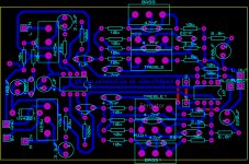
Here is the amp pcb I designed, modifying it with the pot at the input as you said:
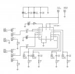
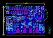
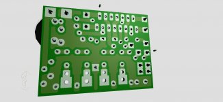
It's cramped because I have a board that size already cutted and I hate cutting board. In the case of the 2 caps superimposing, the 2200uF actually goes sideways out of the board.
Only audio ground, which is hardly avoidable. Otherwise, each power supply is galvanically isolated from the mains, with only a bit of capacitive coupling.I will use two power supplies (hoping the notebook charger will not give me problems with the amp, I will use a 2000uF 35v, 100nF, some other similar, and probably a 1000uF caps to smooth a bit at least), but in the end they will have to join grounds, right?
SMPS aren't necessarily very fond of major additional capacitance on their output - you may have to downsize if your intended values trigger the overcurrent protection on startup.
Everything else can (and should) remain as-is no problem. The idea is to use the original volume pot as your main volume, the new level trim is more of a "set once and adjust rarely if at all" kind of affair.And should I leave the output capacitor there or remove it?
And the original volume pot, do I remove it? If I do can I use it in the position you say? It's 25k log.
And if I do all that should I leave the other input components as they are?
Hey, should I remove the 1uF cap between stages?
Looks like a pretty decent layout overall AFAICS. If you want the flexibility to be using a single power supply in the future, you'd still have to look for a convenient spot to separate input ground and power ground (and join via a bridge if needed).Here is the amp pcb I designed, modifying it with the pot at the input as you said:
View attachment 815736
View attachment 815737
View attachment 815738
What irks me a bit is seeing the output Zobel network directly sharing a ground with the input. The Zobel usually is a case for a small loop area, output-side ground return.
Last edited:
Only audio ground, which is hardly avoidable. Otherwise, each power supply is galvanically isolated from the mains, with only a bit of capacitive coupling.
[...]
If you want the flexibility to be using a single power supply in the future, you'd still have to look for a convenient spot to separate input ground and power ground (and join via a bridge if needed).
[...]
What irks me a bit is seeing the output Zobel network directly sharing a ground with the input. The Zobel usually is a case for a small loop area, output-side ground return.
Can I see an example of what you are saying? I simply don't know how to do this.
-----
BTW, I was reading this message from you in another thread ("my notes" 🙂 ) :
Going single supply isn't that hard though.
1. You need a clean +Vs/2 reference.
2. Inverting opamp circuits: (+in) gets referenced to +Vs/2 instead of "real" ground.
3. Noninverting opamp circuits:
a) (+in) input bias resistor referenced to +Vs/2 instead of "real" ground.
b) Feedback goes to ground via a suitable large coupling capacitor. (You could use +Vs/2 but it often can't take much of a load and/or isn't as low in impedance as you'd like.)
4. Since the circuitry is now operating around +Vs/2, ground-referenced inputs and outputs need coupling capacitors to reflect that.
5. Opamp supplies: V+ = +Vs, V- = GND.
...and I'm not entirely sure what you mean in the 4th point.
(yeah, I have a problem with ground...)
- Home
- Source & Line
- Analog Line Level
- Turning a weird headphones amp into a preamp