Virgin Monkeys with dancing shoes usually.
But during lunch break, they just drop the resistors on the floor, and the heavier end that hits the floor first gets the arrow head.
You should see how they do the Cryo tubes! They dunk them in Super Glue and then dunk them in liquid N2. The Super Glue soaks into all the contraction cracks in the glass to keep them sealed.
Last edited:

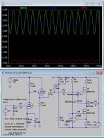
Thought this was an interesting picture to post.
yes an interesting photo but we already knew that it wasn't a wrapped thread.
The problem is, we can't see everything with our eyes.
GREY design:
[1] R10 is rather low for an all-purpose amplifier. I prefer 22 kΩ to 47 kΩ, standard value.
> Yes the my final value is 2 x 220k so 110K to be driven by any source
[2] C4 is ridiculously oversized. Using formula
C = 159,000 / RF
where
R = 2800 Ω
F = 10 Hz
we get
C = 159,000 / ( 2800 × 10 )
C = 5.7 µF
See? I fully understand “plussing up” to the next, or next-next nearest common value, since in this position, precision of the capacitor isn't desired. So, 6.8 µF or 10 µF, would be perfect. Choosing 200+ µF just enhances this amplifier's ability to reproduce wow-and-flutter-and-rumble. Not desired.
> There are other 2 low pass capacitor, the interstage and the output caps so I prefer to keep this very low but 22uF should be enought, I need to simulate it.
[3] R13 being equal to R11 is nigh-short of useless. Do try harder! 22 kΩ, 5 W is a much better choice. Much sturdier driving capability. Still only 7.8 mA nominal.
> I have seen more distortion using lower value for R13
The right side of the design has no values, so… moving to:
WHITE design:
[4] R10, 11 being dual-ganged is mind-bogglingly pointless: the one thing you do not need when creating a resistor-tapped voltage divider that will be supplying nearly no current to the amplifying MOSFETs is to have it drawing large amounts of current. Seriously! That's what C3 is for!
… the better values would have been R9 = 22 kΩ, R3 = 12 kΩ, and R11 = 5 kΩ. Multiturn or not, hardly matters.
R10,R11 are two positions on pcb to mount vertical and orizzontal type
> yes the current on this set could be reduced
[5] No reason to double up R6, 7. Not for power dissipation, not for noise reduction, not for anything I can think of.
> see note about the resistors on signal path
[6] No reason to double up R4, 5, either. Same reasons.
> see note about the resistors on signal path
[7] There's no value for RBIAS. Except for it being a 5 watt resistor. Which does not seem unreasonable!
> Ibias = 0.6V / rbias
[8] Not sure what the 1.0 kΩ, 2 W resistor is for across the output. Safety?
> To load the outptu capacitor if no load is apply
[9] The same critique № 4 applies to R8, 13. They do NOT need to be anywhere near as low-value as stated on the circuit diagram. Just wasting power, to no benefit.
> yes the current on this resistors could be reduced
[10] C5 is significantly undersized. Since you have a power supply around 40 V, and you're planning on delivering quite a few amps in peak output, the optimum value is around 22,000 µF.
> The more important cap. is the main after the rectifier I use 4700uF or 10000uF
> the current absorbed by this amplifier is constant therefore it must not be accumulated in the capacitors to supply peaks
Starts with a 'K', formerly 'A'.No, but there is a little difference in the sound creating the parallel without change the direction.
Many years ago the owner of a company that builds very expensive tube amps taught me this trick.
🙂
I do the same. Why? It sounds better that way.
'It halves things and doubles other things'.
To the other guys, the 'if I cant s'plain it doesn't existerit' type: stay at home, mammas soon coming with soup - watch CNN and play with your train-set. Lovely Jublies.
Imagine all these guys now standing around looking at their plate load and cathode bias resistors..
BTW I was serious once or was that twice?.
Last edited:
No, but there is a little difference in the sound creating the parallel without change the direction.
Many years ago the owner of a company that builds very expensive tube amps taught me this trick.
🙂
This basically nullifies the value of this thread and its subject.
This basically nullifies the value of this thread and its subject.
Bingo.
Sorry I didn't think to create this huge problem with my statement.
I have prepared 2 positions on the PCB for a parallel of 2 resistors, those who want to follow me will use 2 resistances as indicated, those who do not want to compromise will use the Caddock MK132, those who do not believe in anything will use only one resistance.
🙂
I have prepared 2 positions on the PCB for a parallel of 2 resistors, those who want to follow me will use 2 resistances as indicated, those who do not want to compromise will use the Caddock MK132, those who do not believe in anything will use only one resistance.
🙂
This basically nullifies the value of this thread and its subject.
Post #24 provides excellent tips for calming down.
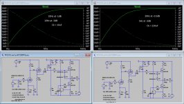
audiodesignguide₃;6076843 said:Ck 10µF seems too low but 100µF is enough
Sorry, and on what basis is 10 µF too low from the attached bode plots? At 20 Hz, the response is at most –1 dB, compared to –½ dB.
Certainly not audible. Except possibly elephants.
⋅-=≡ GoatGuy ✓ ≡=-⋅
All the resistors on the signal path are created with a parallel of two resistors in opposite phase and obviously with the double value.
This allow to use normal 1% resistors and get a sonic result near to the MK132 Caddock considered my reference.
please allow me to hazard a guess, since film type resistors are sort of surface wound, parallelling them in opposite direction lowered the inductance some...

but i doubt that it is needed at all.....
Sorry, and on what basis is 10 µF too low from the attached bode plots? At 20 Hz, the response is at most –1 dB, compared to –½ dB.
Certainly not audible. Except possibly elephants.
⋅-=≡ GoatGuy ✓ ≡=-⋅
i remember many years ago, it was SY who told me that his mentor told him to use the smallest value capacitor for coupling that he could get away with...i would say goes for bypass too....i have since included that to my bag of tricks...there are a lot of tricks in this board for the pickings, but sadly, many still prefer the snake oil stuf....
but hey, this is diy, where most are not engineers anyway, so part of having fun is doing the unthinkable, as long as you do not injure yourself....... 😀....
i remember many years ago, it was SY who told me that his mentor told him to use the smallest value capacitor for coupling that he could get away with…i would say goes for bypass too....i have since included that to my bag of tricks…there are a lot of tricks in this board for the pickings, but sadly, many still prefer the snake oil stuf....
but hey, this is diy, where most are not engineers anyway, so part of having fun is doing the unthinkable, as long as you do not injure yourself....... 😀....
Hey, hey … the bar keeps getting lower and lower.
Anyway, having toured a resistor-making plant a decade back, where admittedly not much has changed in the last 20 years!, the resistors (film) are 'blasted' onto the ceramic form, on top of a 'resist' layer which is spin-printed first. Baked. Then the resist — being water soluble — is just washed off, and the resistor 'stuff' is washed away.
The resulting resistors have values “all over the place”, but more-or-less also where the manufacturer intends. They're individually rapidly tested, stressed and sorted into bins. Then, when a bin is near-full, they're dumped into a marking machine, and spun up with pretty colored paint.
If you're still reading, it should be patently obvious that by this point, there is no relationship between the markings, and whatever magical 'orientation' the double-resistor-in-reverse theory hopes to “straighten out”.
Which … in net … is my 'redux' of magical-handwaving-theory. Doing ostensibly rational (or rationalized) things, in order to cure a not-really—real problem, and because so much of the audiophile scene is oohing and ahhing about the precision, the remarkable accuracy, the amazing soundstage and presence … of a barely well-controlled A-B listening-after-making-lots-of-changes experiment … well, no more needs saying.
Reverse the resistors if that makes one's rocks jiggle. Might want to do that with inductors too, and might as well the same for output transformers, if used. Everything in parallel! Seriously … if a little snake oil is good, then a BIG bucket of it ought to be better, right?
I'm tired, and bitter, today.
So, to anyone offended, I apologize.
To anyone woke enough to hear a scintilla of objective dissonance, …
There you are.
⋅-⋅-⋅ Just saying, ⋅-⋅-⋅
⋅-=≡ GoatGuy ✓ ≡=-⋅
Hi Tony,
'back in the day' (too many years/tears ago!) the 'better' studio people used propylene film/foil caps and maybe the Roedestein MF resistors (or even those Manganin or Isotan types) - the caps have developed quite a bit (and the prices!), but the resistors haven't changed much at all.
I disagreed with Mr Yanager about a few things and component choices was one of them, but we all have our own particular 'favourites' and attitudes, eh!
Curiously, I did build this 'power follower' quite a few years ago and it's still in operation today (with the Voxativ in OB) - it now has the "Bijou' headlamp type regulated tube power supply and a 'capacitor multiplier' supply for the fets - the amp build isn't particularly expensive (except the tubes) and a good Diya project, IMHO.
one can only sigh a sigh of disappointment to see people, more often than not are easy to embrace the snake oil stuff more easily, than trying to learn the basic but better stuff...
the power follower is a simple but good design, Pavel, and NP's MOFO are seen here in this thread...
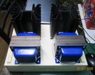
i am making a mofo myself, i wound my own chokes that i am using, chokes are used instead of CCS....
i am making a mofo myself, i wound my own chokes that i am using, chokes are used instead of CCS....
Attachments

Starts with a 'K', formerly 'A'.
I do the same. Why? It sounds better that way.
'It halves things and doubles other things'.
To the other guys, the 'if I cant s'plain it doesn't existerit' type: stay at home, mammas soon coming with soup - watch CNN and play with your train-set. Lovely Jublies.
Imagine all these guys now standing around looking at their plate load and cathode bias resistors..
BTW I was serious once or was that twice?.
God dang it, you made my soup come out of my nose.
Nice. I too have the Vas issue. My front end follower is using a CRD in the negative supply. Attached pic from Tektronix Tube Circuits.(Cathode resistor replaced with current reg diode)
With +-15vdc supply have 6vrms input compliance.
6Sn7 , very low distortion and no high order harmonics. H2 is dominant with 3rd close to floor. DC coupled input.
What software are you using?
Do you use a regulated negative voltage to set the correct 1/2 Vcc ?
the power follower is a simple but good design, Pavel, and NP's MOFO are seen here in this thread...
i am making a mofo myself, i wound my own chokes that i am using, chokes are used instead of CCS....
MOFO follow the design of Inpol amplifiers by Pathos (pathosacoustics.com).
https://www.diyaudio.com/forums/solid-state/10258-pathos-amplifiers.html#4
The advantage with this configuration is certainly a double efficiency compared to the power follower but 2 advantages are lost:
1) The discoupling of the signal current from power supply because the current generator has a huge impedance (an open circuit for the signal, in theory)
2) The constant current flow from the power supply also during the music peaks that prevent any stress of the power supply.
To add one big problem: the construction of a stratified inductance to guarantee a good bandwidth is not easy and expensive.
I remember some my simulations about this circuit, the value should be about 0.1H for a full range amplifier.
What type are you using ?
Last edited:
- Home
- Amplifiers
- Tubes / Valves
- the Power Follower - after 20 years a new test