I own a HAPI 2 preamp designed by Stewart Hegeman. It features a time-delayed relay circuit on the outputs that provides an ~5 second delay after power-up before the preamp's output goes live. The problem is, the relays cause a terrible thump in my speakers when they engage and disengage.
The thump changes based on the capacitance.
When I changed the size of the cap, I expected the delay time to change, obviously. But I don't quite understand why it would effect the loudness of the thump, and why it would do so differently on startup and shutdown.
Can someone help me to understand it?
And is there are way to fix it (eliminate the thump)?
I know enough to basically understand how the circuit functions (R/C combo delays the transistor from switching the circuit on until the cap charges). But I don't understand it enough to figure out the above.
***Edit: I'm not 100% sure where exactly to fit this thread in the forum, but since this sub-forum is home to several threads about soft starts and circuits with a similar purpose, this seemed to be the appropriate place. Please pardon my error if it was not ***

The thump changes based on the capacitance.
- With the circuit configured as drawn (the original configuration) the relays cause a loud thump when they engage and a louder thump when they disengage.
- If I halve the capacitance, the thump is still slightly quieter, but equal on startup and shutdown.
- If I double the capacitance, the thump is nearly gone when the relays engage, but very loud when they disengage.
When I changed the size of the cap, I expected the delay time to change, obviously. But I don't quite understand why it would effect the loudness of the thump, and why it would do so differently on startup and shutdown.
Can someone help me to understand it?
And is there are way to fix it (eliminate the thump)?
I know enough to basically understand how the circuit functions (R/C combo delays the transistor from switching the circuit on until the cap charges). But I don't understand it enough to figure out the above.
***Edit: I'm not 100% sure where exactly to fit this thread in the forum, but since this sub-forum is home to several threads about soft starts and circuits with a similar purpose, this seemed to be the appropriate place. Please pardon my error if it was not ***
Attachments
Last edited:
I found a similar thump caused by a Teledyne TO5 relay switching inputs to a data acquisition system analog input. (Texas Instruments DFS2). I think the electric field caused by the relay coil acted on the contact gap to produce a voltage on the high impedance input of the DAQ.
I think something more useful could be generated by a CD4066 transmission gate IC. datasheet is available from datasheetcatalog.com
I'm unable to determine whether the input passes with control high or low, but there shouldn't be much pop. A timer consisting of a 1 uf ceramic cap and a 1 meg pull up resistor should provide a 1 second off period during power up. Of course the signal has to be between upper & lower power supply voltages of the IC, which can be as much as 18 v apart. If the signal is between +-15 v , there are other more expensive transmission gate IC's available.
A CD4093 schmitt trigger nand gate could be used to sense the RC timer, preventing possible oscillation during the maybe state of the control input (~1/3 to 2/3 of power supply) .
Other gates could be used to determine power was going down and pull the control to off state during that period.
Warning, CMOS is static sensitive, collar your wrist to safety ground when handling in dry (winter) environments.
Last edited:
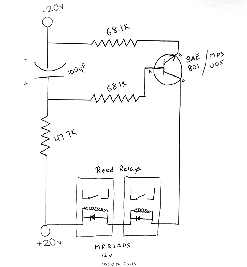
47k7 -> 47k4; Trc = 47k4 * 100μ = 4.7sec; Q kicks in before this time
68k1 -> 68k2; when on Ic = (40 - 12) / 68k2 = 0.4mA: low value
If the audio circuit pops, there, and not elsewhere, a charge is released.
So the value of the cap will not change the pop, maybe the 'attack' of the reed.
Try bleeders to gnd on both side of the switching contacts, say 100k.
68k1 -> 68k2; when on Ic = (40 - 12) / 68k2 = 0.4mA: low value
If the audio circuit pops, there, and not elsewhere, a charge is released.
So the value of the cap will not change the pop, maybe the 'attack' of the reed.
Try bleeders to gnd on both side of the switching contacts, say 100k.
I'd go along with MarsBravo's suggestion of bleeder resistors.
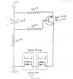
The circuit obviously works if you get a 5 second delay and the delay responds to the cap value. I'm not sure the circuit is drawn correctly though... 1000 ohm coils and 68k emitter resistor but that doesn't matter if it delays correctly.
If you try Mar's 100k suggestion then you should also measure the DC voltage at the preamp output socket which should be zero volts DC at all times.
I wonder if the relays are in series with the audio rather than operating as a shunt to ground.
I'd go along with MarsBravo's suggestion of bleeder resistors.
The circuit obviously works if you get a 5 second delay and the delay responds to the cap value. I'm not sure the circuit is drawn correctly though... 1000 ohm coils and 68k emitter resistor but that doesn't matter if it delays correctly.
If you try Mar's 100k suggestion then you should also measure the DC voltage at the preamp output socket which should be zero volts DC at all times.
I wonder if the relays are in series with the audio rather than operating as a shunt to ground.
Thanks. I'll try his suggestion and see if that helps.
I checked DC offset very quickly and found none, but I'll keep my meter attached for a while and see if anything changes as it idles for a while.
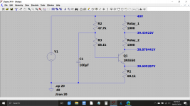
The resistor values are correct, and I believe the circuit is drawn correctly. You can see it yourself using the photo attached to the first post. The only questionable item is the spec for the relays. Information was hard to come by. One old catalogue I found said the coil resistance was 1K, another said 1.4K.
Last edited:
I was thinking that 40 volts across 68.1k + the relay coil resistance (so say 70.1k in total) only gives a current of 0.6 milliamps which would develop just 0.6 volts across each coil.
That doesn't sound right to me. The relays are marked 12 volts.
Reverse engineer from the relay voltage and we need 24 volts across 2k which means 12 milliamps is needed.
40 volt total supply less 24 volts for the two series relays means that 16 volts is to be 'lost' across the resistor and so that would come in at approx 1.3k.
Have you measured the emitter resistor?
Agree that thump comes from DC imbalance on both sides of switches and not from relay driving itself.
Unless you have absolutely horrible grounding, which I find hard to exist in a professionally made preamp.
Unless you have absolutely horrible grounding, which I find hard to exist in a professionally made preamp.
I'm going to measure everything when I get home to verify the resistances and voltages.
Here's what's installed in the circuit, and how I interpreted it by reading the color codes:
Blue, Grey, Brown, Red, White = 68.1K
Blue, Grey, Red, Red, White = 68.2K
Yellow, Violet, Yellow, Red, White = 47.4K
I was off by a few hundred ohms on two of them.
And while I was flummoxed by the last band being white, I did measure another resistor (which I know to be 47.3K) and it's color code was Yellow, Violet, Orange, Red, White. So I think I am reading them correctly.
***EDIT: and if they were 4 band with an inexplicable white 5th band, then the resistor I marked at 47.4K would actually be a 470K resistor, making the RC time constant 47 seconds. Unlikely, since it was meant to be a 5 second delay, corresponding to a 47.4K resistor. Also: I have owned 4 of these, and all of them had the same resistors in the same place. So, I'm pretty sure what I drew is correct, and as intended by the designer.***
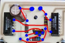
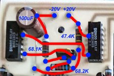
I have also attached a very large photo of the actual circuit board. I traced the traces in red and connections in blue. Correct me if I'm wrong, but the schematic I drew is correct (pending verification of the resistance values).
Here's what's installed in the circuit, and how I interpreted it by reading the color codes:
Blue, Grey, Brown, Red, White = 68.1K
Blue, Grey, Red, Red, White = 68.2K
Yellow, Violet, Yellow, Red, White = 47.4K
I was off by a few hundred ohms on two of them.
And while I was flummoxed by the last band being white, I did measure another resistor (which I know to be 47.3K) and it's color code was Yellow, Violet, Orange, Red, White. So I think I am reading them correctly.
***EDIT: and if they were 4 band with an inexplicable white 5th band, then the resistor I marked at 47.4K would actually be a 470K resistor, making the RC time constant 47 seconds. Unlikely, since it was meant to be a 5 second delay, corresponding to a 47.4K resistor. Also: I have owned 4 of these, and all of them had the same resistors in the same place. So, I'm pretty sure what I drew is correct, and as intended by the designer.***
I have also attached a very large photo of the actual circuit board. I traced the traces in red and connections in blue. Correct me if I'm wrong, but the schematic I drew is correct (pending verification of the resistance values).
Attachments
Last edited:
I wonder if the relays are in series with the audio rather than operating as a shunt to ground.
Mooly, can you expand on this?
I see 470K, 6.8K, & 680 ohms, all 2% tolerance. I think the white stripe is some kind of failure rate code, though I can't remember the details on that.
Mooly, can you expand on this?
If the relay contacts are in series with the audio then the audio has to normally flow through the contacts from one side of the relay to the other. The problem with that is that any deterioration of the contacts can cause noise and non linear type distortions. We see that a lot in larger speaker relays.
A shunt arrangement actually has the relay wired so that it shorts the audio to ground. Only when the contact open does audio get through. This arrangement takes the quality of contact out of the equation and is considered a better approach these days.
I see 470K, 6.8K, & 680 ohms, all 2% tolerance. I think the white stripe is some kind of failure rate code, though I can't remember the details on that.
I did measure another resistorat 47.3K and its color code was Yellow, Violet, Orange, Red, White. So I think I am reading them correctly.
Plus, the circuit was designed to give a 5 second delay, which corresponds to 47K with 100uF. If that resistor were 470K, the delay would be 47 seconds.
We'll know for sure when I get home and measure them.
Last edited:
If the relay contacts are in series with the audio then the audio has to normally flow through the contacts from one side of the relay to the other. The problem with that is that any deterioration of the contacts can cause noise and non linear type distortions. We see that a lot in larger speaker relays.
A shunt arrangement actually has the relay wired so that it shorts the audio to ground. Only when the contact open does audio get through. This arrangement takes the quality of contact out of the equation and is considered a better approach these days.
These are definitely in series, though I don't think that's the issue here. I replaced the relays in another one of these that I owned in an attempt to fix the issue, and the thump remained entirely unchanged.
Series feed was very commonly used, I just wondered that's all 🙂
More of a puzzle to me are your resistor values... do you see how the 68.1k value doesn't make sense. Even if you applied the full 40 volts available directly across the resistor you would only get 0.59 of a milliamp to flow. That is never going to operate a relay.
You can't measure values in circuit accurately, you have to lift one end of the part to isolate it. It would be worth doing that for that resistor, just to see what it really is.
It's 680R, 6k8 and 470k The red ring is 200 ppm tempco so you should look at only three rings. Red and silver is tempco and tolerance.I'm going to measure everything when I get home to verify the resistances and voltages.
Here's what's installed in the circuit, and how I interpreted it by reading the color codes:
Blue, Grey, Brown, Red, White = 68.1K
Blue, Grey, Red, Red, White = 68.2K
Yellow, Violet, Yellow, Red, White = 47.4K
Last edited:
And with 680 ohms we get a delay of sorts but its not good because the transistor comes into conduction very slowly. This mean the delay isn't dependent on the timing components on their own but also factor in the point at which sufficient voltage is developed across the relay for them to close.
This is bad design imo because relays should ideally close with a definite snap action, and not close slowly with a lazy rising voltage.
I'm sorry but no one seems able to see all this 🙂
Time to eat I think.
This is bad design imo because relays should ideally close with a definite snap action, and not close slowly with a lazy rising voltage.
I'm sorry but no one seems able to see all this 🙂
Time to eat I think.
Attachments
- Home
- Amplifiers
- Power Supplies
- Improving Very Simple Time Delay Circuit