If you are looking for an extreme quality amplifier and you don't need high power this is the project for you because nothing can have higher performances.
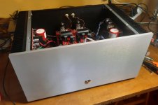
After 20 year I have rebuild the same project because this is perfect on all aspects except the efficiency but this is normal for a true single ended class A.
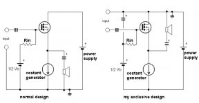
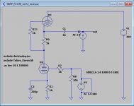
This project is an hybrid amplifier composed by a tube voltage amplifier followed by a single ended mosfet current amplifier with an exclusive configuration.
I have published several articles about this my current amplifier and this design was the winner of the award in the Circuit ideas in May 2000 on Electronics World which is the most important electronic magazine in the world.
This amplifier was built by a lot of people around the world and everyone are enthusiastic about the result, the sound is compared to that of the best single ended vacuum tube amplifiers but this have a higher performances in terms of driving capacity (damping factor) and low distortion.
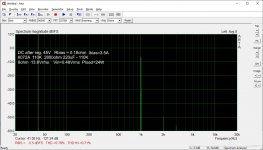
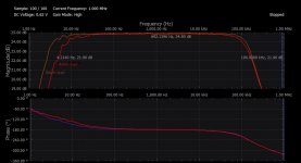
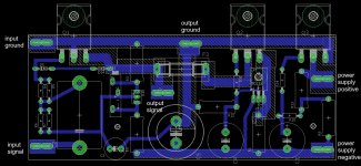
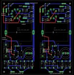
Here the measurements and the files to produce the pcb.
After 20 year I have rebuild the same project because this is perfect on all aspects except the efficiency but this is normal for a true single ended class A.
This project is an hybrid amplifier composed by a tube voltage amplifier followed by a single ended mosfet current amplifier with an exclusive configuration.
I have published several articles about this my current amplifier and this design was the winner of the award in the Circuit ideas in May 2000 on Electronics World which is the most important electronic magazine in the world.
This amplifier was built by a lot of people around the world and everyone are enthusiastic about the result, the sound is compared to that of the best single ended vacuum tube amplifiers but this have a higher performances in terms of driving capacity (damping factor) and low distortion.
Here the measurements and the files to produce the pcb.
Attachments
Last edited:
If you are looking for an extreme quality amplifier and you don't need high power this is the project for you because nothing can have higher performances.
After 20 year I have rebuild the same project because this is perfect on all aspects except the efficiency but this is normal for a true single ended class A.
This project is an hybrid amplifier composed by a tube voltage amplifier followed by a single ended mosfet current amplifier with an exclusive configuration.
I have published several articles about this my current amplifier and this design was the winner of the award in the Circuit ideas in May 2000 on Electronics World which is the most important electronic magazine in the world.
This amplifier was built by a lot of people around the world and everyone are enthusiastic about the result, the sound is compared to that of the best single ended vacuum tube amplifiers but this have a higher performances in terms of driving capacity (damping factor) and low distortion.
0
Was this translated using Google Superlative? 😀
In all seriousness, thank you for contributing your work to the community!
Was this translated using Google Superlative? 😀
In all seriousness, thank you for contributing your work to the community!
🙂
I am sure of the result because I have tested many other design from vacuum tube single ended to hi-end hybrid solid state.
Here the files to produce the PCB ad the table to calculate the output power with different voltage and current.
Attachments
Last edited:
Nice. I too have the Vas issue. My front end follower is using a CRD in the negative supply. Attached pic from Tektronix Tube Circuits.(Cathode resistor replaced with current reg diode)
With +-15vdc supply have 6vrms input compliance.
6Sn7 , very low distortion and no high order harmonics. H2 is dominant with 3rd close to floor. DC coupled input.
What software are you using?
With +-15vdc supply have 6vrms input compliance.
6Sn7 , very low distortion and no high order harmonics. H2 is dominant with 3rd close to floor. DC coupled input.
What software are you using?
Attachments

One option is the SRPP (Shunt Regulated Push-Pull) tube amplifier with ECC88/6922 like used in the old Bartolomeo Aloia pre-ampl.
Rout about 500ohm
Av about 31dB
These are perfect parameters to be integrated with the Power Follower current amplifier stage.
Many years ago I tested the SRPP and the sound was not liked because it seemed very cold compared to a normal common cathode triode amplifier but it could be interesting to make new tests on this configuration.
Attachments
Last edited:
Since you're overtly promoting your design, I feel it important to note a few things.
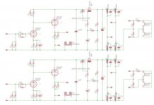
GREY design:
[1] R10 is rather low for an all-purpose amplifier. I prefer 22 kΩ to 47 kΩ, standard value.
[2] C4 is ridiculously oversized. Using formula
[3] R13 being equal to R11 is nigh-short of useless. Do try harder! 22 kΩ, 5 W is a much better choice. Much sturdier driving capability. Still only 7.8 mA nominal.
The right side of the design has no values, so… moving to:
WHITE design:
[4] R10, 11 being dual-ganged is mind-bogglingly pointless: the one thing you do not need when creating a resistor-tapped voltage divider that will be supplying nearly no current to the amplifying MOSFETs is to have it drawing large amounts of current. Seriously! That's what C3 is for!
… the better values would have been R9 = 22 kΩ, R3 = 12 kΩ, and R11 = 5 kΩ. Multiturn or not, hardly matters.
[5] No reason to double up R6, 7. Not for power dissipation, not for noise reduction, not for anything I can think of.
[6] No reason to double up R4, 5, either. Same reasons.
[7] There's no value for RBIAS. Except for it being a 5 watt resistor. Which does not seem unreasonable!
[8] Not sure what the 1.0 kΩ, 2 W resistor is for across the output. Safety?
[9] The same critique № 4 applies to R8, 13. They do NOT need to be anywhere near as low-value as stated on the circuit diagram. Just wasting power, to no benefit.
[10] C5 is significantly undersized. Since you have a power supply around 40 V, and you're planning on delivering quite a few amps in peak output, the optimum value is around 22,000 µF.
NET… i'm sure the amplifier sounds just fine. Great even. But it has power-wasting design overkill which doesn't accomplish anything in the end. Maybe it is a personal ideal, but I really prefer “right sizing” components from a position of mathematical justification. I've never — ever — had a mathematically 'sound design' amp fall short of the design due to an unforseen problem that 'over-design' would have invisibly cured.
⋅-⋅-⋅ Just saying, ⋅-⋅-⋅
⋅-=≡ GoatGuy ✓ ≡=-⋅
GREY design:
[1] R10 is rather low for an all-purpose amplifier. I prefer 22 kΩ to 47 kΩ, standard value.
[2] C4 is ridiculously oversized. Using formula
C = 159,000 / RF
whereR = 2800 Ω
F = 10 Hz
we getF = 10 Hz
C = 159,000 / ( 2800 × 10 )
C = 5.7 µF
See? I fully understand “plussing up” to the next, or next-next nearest common value, since in this position, precision of the capacitor isn't desired. So, 6.8 µF or 10 µF, would be perfect. Choosing 200+ µF just enhances this amplifier's ability to reproduce wow-and-flutter-and-rumble. Not desired.C = 5.7 µF
[3] R13 being equal to R11 is nigh-short of useless. Do try harder! 22 kΩ, 5 W is a much better choice. Much sturdier driving capability. Still only 7.8 mA nominal.
The right side of the design has no values, so… moving to:
WHITE design:
[4] R10, 11 being dual-ganged is mind-bogglingly pointless: the one thing you do not need when creating a resistor-tapped voltage divider that will be supplying nearly no current to the amplifying MOSFETs is to have it drawing large amounts of current. Seriously! That's what C3 is for!
… the better values would have been R9 = 22 kΩ, R3 = 12 kΩ, and R11 = 5 kΩ. Multiturn or not, hardly matters.
[5] No reason to double up R6, 7. Not for power dissipation, not for noise reduction, not for anything I can think of.
[6] No reason to double up R4, 5, either. Same reasons.
[7] There's no value for RBIAS. Except for it being a 5 watt resistor. Which does not seem unreasonable!
[8] Not sure what the 1.0 kΩ, 2 W resistor is for across the output. Safety?
[9] The same critique № 4 applies to R8, 13. They do NOT need to be anywhere near as low-value as stated on the circuit diagram. Just wasting power, to no benefit.
[10] C5 is significantly undersized. Since you have a power supply around 40 V, and you're planning on delivering quite a few amps in peak output, the optimum value is around 22,000 µF.
NET… i'm sure the amplifier sounds just fine. Great even. But it has power-wasting design overkill which doesn't accomplish anything in the end. Maybe it is a personal ideal, but I really prefer “right sizing” components from a position of mathematical justification. I've never — ever — had a mathematically 'sound design' amp fall short of the design due to an unforseen problem that 'over-design' would have invisibly cured.
⋅-⋅-⋅ Just saying, ⋅-⋅-⋅
⋅-=≡ GoatGuy ✓ ≡=-⋅
Goatguy , too much *drama• or I would read your entire "analysis".
My loss … lost a reader! Oh well, I was just countering “the self-promotional style” of the OP philosophically. Sure, I could trim out the “ridiculous” and other almost gratuitous jargon, but what's the fun in that? LOL… ⋅-=≡ GoatGuy ✓ ≡=-⋅
@jfetter; I thought that too about Joe_Rasmussan_guy, until I saw a piece outside of DIYAudio and concluded the guy just writes that way. Lots emphatic hyper-text markup style...
(At one point I wondered how does he get all the colors and bolds and fonts in here...)
(At one point I wondered how does he get all the colors and bolds and fonts in here...)
@jfetter; I thought that too about Joe_Rasmussan_guy, until I saw a piece outside of DIYAudio and concluded the guy just writes that way. Lots emphatic hyper-text markup style…
(At one point I wondered how does he get all the colors and bolds and fonts in here…)
Its a good observation.
I wrote (in PERL) a comment-preprocessor, which translates.
So, for instance, I can enter
This _is underlined #and bold#_
and have it come out as This is underlined and bold
without having to do any keying in of the [ {tag} ] … [ /{tag} ] business. Same goes for chemical formulæ, (and translating the 'ae' on that to the single HTML character!). That way, after a few years of 'many minutes of new rules strung together', my preprocessor has hundreds of neat 'hacks' making it all work. Even my signature:
⋅-⋅-⋅ Just saying, ⋅-⋅-⋅
⋅-=≡ GoatGuy ✓ ≡=-⋅
is typed in as
jsgg
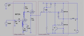
Sorry these are the final components used for the driver stage
R1,R2,R18,R19, 220Kohm 1/2W 1% Mouser 594-MBB02070C2203FCT
R5,R6,R22,R23
R9,R10,R26,R27
R3,R4,R20,R21, 1000ohm 1/4W 1% Mouser 594-MBB02070C1001FC1
R11,R34
R7,R8,R24,R25 5600ohm 1/4W 1% <<< 5600ohm for 6072 and 4000ohm for the 12AX7
R15,R16,R31,E32 220ohm 1/4W 1%
R17,R33 3.3ohm 2W Mouser 660-MOSX2CT52R3R3J
R12,R30 100Kohm 1/4W 1% Mouser 594-MBB02070C1003FCT
R14,R29 150Kohm 3W
R13,R28 18Kohm 2W
C1.C3 220uF 6.3V OS-CON Mouser 667-6SEPC220M+TSS <<< not use for 12AX7
C2,C4 33uF 400V Mouser 647-UVY2G330MHD
C5,C6 100uF 400V Mouser 647-LGU2G101MELZ
CY1-CY8 10nF 440VAC RS 335-066 o 80-R474I210050A1K
U$3,U$6 IRF840 Mouser 844-IRF840APBF
U$11,U$7 33uF 400V Solen MKP
D1,D2,D3,D4,D6,D7,D8,D9 UF5406 Mouser 625-UF5408-E3
D5,D10 zener 10V 1W
KK1,KK4 Extruded Style Heatsink for TO-220 Mouser: 532-513102B25
Isolator Bergquist SP400-0.007-00-54 RS 169-2177
Isolatos TO-220 nylon platstic Insulator hole size M3
The connections are 63862-1 (CUT STRIP) by TE Connectivity / AMP (cod. Mouser 571-63862-1-CT, cod. RS 718-7987)
Using the 6082 in order to keep the Vkf under the max value it is necessary made a modification adding 4 resistors 2 x 56K 1W and 2 x 150K 2W and cut the filament ground wire on pcb.
Attachments
Last edited:
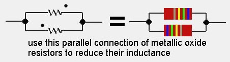
Resistors have a phase now?
No, but there is a little difference in the sound creating the parallel without change the direction.
Many years ago the owner of a company that builds very expensive tube amps taught me this trick.
🙂
No, but there is a little difference in the sound creating the parallel without change the direction.
Many years ago the owner of a company that builds very expensive tube amps taught me this trick.
🙂
Its a trick alright. You should share it with instrumentation designers. They love novel new stuff that improves performance.
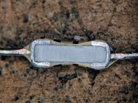
Thought this was an interesting picture to post.
hmm. no arrows, no grain.
Anyone know how the factories align the resistors to ensure correct directionality before marking them?
- Home
- Amplifiers
- Tubes / Valves
- the Power Follower - after 20 years a new test