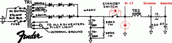
Can someone comment whether the 2 added diodes in red are a useful addition?
After seeing what switch contacts go through when switching even lower voltage DC, probably. Switching AC will have very little arcing, not so with DC. Wondering why Fender did not use a DPST and switch it right off the transformer as AC in front of the rectifiers?
Let's see, I'm going to break a connection that goes between a DC source and two inductors.....Can there possibly be a DUMMER place in the entire amp to put a switch. Yes the diodes will tame the fire inside the switch. Use good ones!
That type of standby switch has been typical in most Fender and Marshall classic amps. How about just putting a 2W 220K resistor across the standby? Merlin recommended 47K 2W but I can't see that working well in the long run. What happens when you apply signal in standby. I guess the 47K will act as a fuse now that I think about it.
A much better idea is to remove the diodes and the switch as it has no benefitCan someone comment whether the 2 added diodes in red are a useful addition?
and is potentially dangerous as firecracker.
If you want a swich to silence the amp try grounding the signal.
To burn out a 2W 47k resistor the output stage would pretty much need to behave like a short circuit to ground. But it can't, not least because it will be operating under starved conditions while the 47k is in place. The 47k will last forever. But you can use a different value if you prefer.Merlin recommended 47K 2W but I can't see that working well in the long run. What happens when you apply signal in standby. I guess the 47K will act as a fuse now that I think about it.
...or place the switch between the diodes and the 1st filter cap arrangement?Wondering why Fender did not use a DPST and switch it right off the transformer as AC in front of the rectifiers?
Best regards!
To burn out a 2W 47k resistor the output stage would pretty much need to behave like a short circuit to ground. But it can't, not least because it will be operating under starved conditions while the 47k is in place. The 47k will last forever. But you can use a different value if you prefer.
I was just testing the 47K in a build:
PP KT88's with a B+ of about 472VDC.
In standby there was about 290VDC across the 47K resistor which is dissipating about 1.8W. I didn't try strumming a guitar through it (a Soldano SLO100 type build).
Guitar players are finicky - they want standby switches.
I agree, switching the AC just before the diodes is a better option.
...or place the switch between the diodes and the 1st filter cap arrangement?
Best regards!
Sure, anywhere prior to smoothing would be easier on the contacts as the rectified wave would inherently have some valleys to extinguish the fire?
Why would Fender (then Marshall and others) do it that way? Fwiw, it is my opinion that few of them failed after 50+ years. Many, probably >1,000,000, are still in active service.
I don't know why fender chose that method, but typically what i see is the standby breaking the ground connection of the center tap on the transformer.
I don't know why fender chose that method, but typically what i see is the standby breaking the ground connection of the center tap on the transformer.
I did that years ago, but I found an audible SNAP when switching
The real question is "Why even bother with standby" ? It does not make life easier to the tubes, it does exceed the common switches ratings, and it opens up an operational issue.
If one wants to silence an amp, then ground the signal !
If one wants to silence an amp, then ground the signal !
Single pole switch was cheaper than a double pole. Fender built to cost.Why would Fender (then Marshall and others) do it that way?
To quote myself:
In almost a century of valve technology the only audio amps ever to use standby switches were guitar amps. Why? The trend began with the more powerful versions of the Fender Bassman (the 5E6 I think). Some people have suggested that it was primarily intended as a kind of mute switch, allowing the amp to be silenced between songs without needing to wait for it to warm up again before the next song. This is not a compelling argument since there are much cheaper ways to mute an amp without needing a heavy-duty high-voltage switch. Also, you would expect competing manufacturers to have provided similar mute switches on their amplifiers, but none did.
Another theory suggests the switch was added to amps which used silicon rectifiers because they did not provide the natural 'soft start’ of the original valve rectified designs. This is obviously untrue, however, since the first Bassman amps fitted with standby switches were still built with valve rectifiers.
There are two plausible explainations for the added standby switch. One is that is helped to protect the power supply capacitors from excessive voltage before the valves start to conduct and pull the voltages down to normal levels. Fender often used a reservoir capacitor rated for higher voltage than the smoothing caps after the standby switch, which must have saved money and space. Take a look at the 5E6 Bassman for example. The 135 Bassman schematic even shows labelled voltages, exceeding the cap ratings during standby.
The other possibility is that the 5E6 was the first amp where Fender used a DC-coupled cathode follower. This stage will sometimes arc between grid and cathode at switch-on if the cathode has not yet warmed up. (These days you should put a diode or neon-lamp between grid and cathode to prevent this, not rely on the user).
Everyone knows Marshall copied the Bassman -complete with standby switch- so we then had the two biggest names using standby switches, only one of which knew why. The other big players, Vox and Gibson, traditionally never used standby switches. Only very recently have they given in and started adding them, presumably out of customer expectation, even though no modern designer (who values his reputiation) uses under-rated power supply capacitors. In fact, when Vox added a standby switch to its re-issue AC30CC they made the big mistake of putting the standby switch between the valve rectifier and the reservoir capacitor (something Fender was careful not to do). This hot-switching lead to several catastrophic rectifier failures on the first production run. Vox had to hastily add a resistor in parallel with the switch to allow the reservoir to charge up during standby.
Last edited:
Can someone comment whether the 2 added diodes in red are a useful addition?
The diode pointing up is the 'Free Wheeling Diode', a place for inductor current to reference when the switch is opened. These are commonly found on switch mode PSs, not common in toob ccts. Just some insurance for the switch. In Olde ccts there would be an RC combo to damp the arc that eats switch contacts while switching DC.🙂
Not sure why the diode across the switch, its unlikely the the RHS will go higher than the LHS, even tho the volts across L might bang around a little. But the vertical diode clamps that point.
Set scope to single shot, set the triggering, than watch the transient on switch off. Some examples here in the pile.
- Home
- Amplifiers
- Tubes / Valves
- Standby Switch + 2 diodes