So you're gunna randomly get mad and leave without even mentioning what your problem is even though I asked nicely.....Okay...
simulators just like calculators can do a quick job at computing, but they do not make you any more smarter if you do not know math and can not do long hand calculations...
There are no simulations here - the simulator is used as the back of a napkin. A working simulation may be a good starting point in this particular thread. Or a working prototype 🙄
I can tell you what it is in power amps.There's ...many types of tube amps.
..the point is to find out what specifically causes the tube sound.
A certain type of non linear compression, which varies subject to the following (non exhaustive list):-
1/ line stability (also exists in microphones)
2/ magnetic saturation characteristics (exists in tape heads also) - transformers.
3/ alignment of grids, especially secondary emission (particularly pentodes)
4/ cathode emission limits and aging, (matching of differing pairs)
5/ leakage inductance and stray capacitance in transformers
6/ quality control issues between different manufacturers NOS and Repro.
7/ Insulation issues between differing electrodes, inc DHTs.
8/ Oscillation phenomena which can be hard to detect...
9/ other parasitic phenoma inc shot noise & microphony
10/ specific behaviour under inductive and capacitive loads.
plenty more 🙂
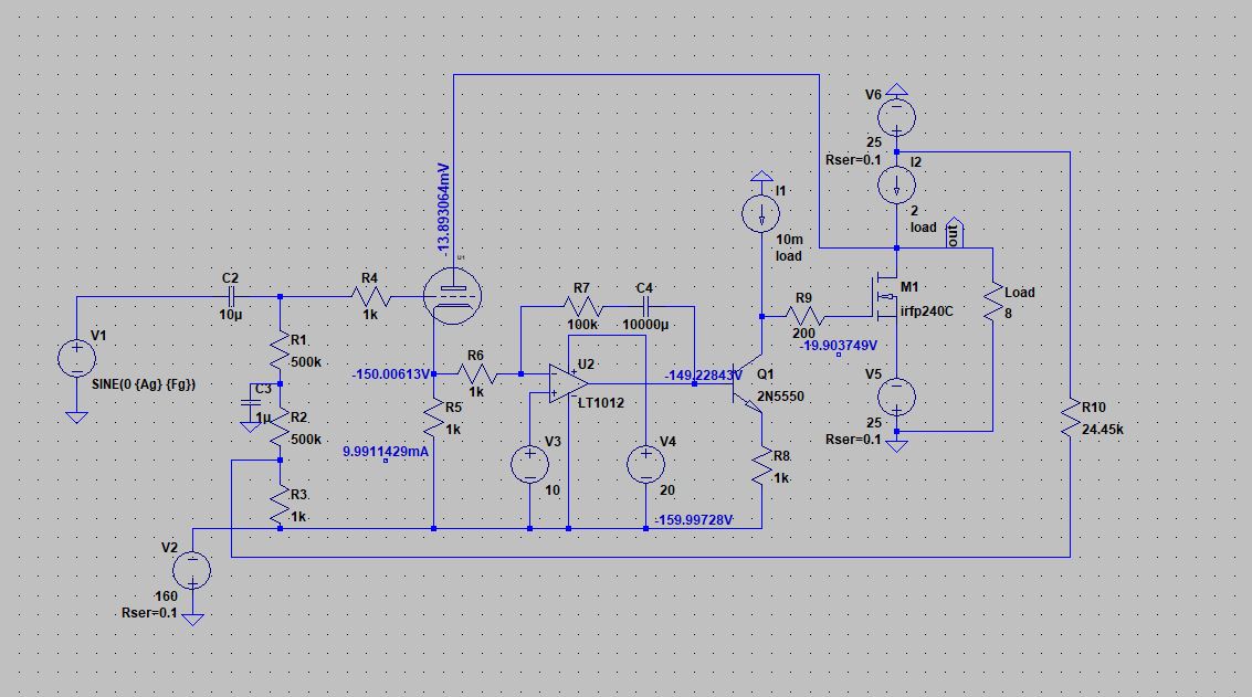
Here is the original schematic rearranged and simplified. I couldn't get the sim to solve with the DC servo so I fudged it with a resistor. Gives about 15W at 0.6% distortion, gain of 22. It's fairly easy to follow and I can see what hellokitty was trying to do, but I have a feeling the same result would be achieved using a CCS loaded common cathode 6SN7 driving a high feedback unity gain buffer. Obviously high frequency performance could be improved and a real circuit would likely require some compensation but as a proof of concept it works.
Attachments
I went down a similar path over 15 years ago, albeit in a much more simplified manner. At the time I was getting some good sound, but the whole thing would just randomly blow up, often violently.
At the time the secondary breakdown phenomenon in BJT's were fairly well known, and it was believed that mosfets were immune from these effects. It is now well known that hot spots on the die do form in mosfets, and do cause them to blow up. It is also known that materials with a lower thermal conductivity than silicon exhibit the problem to a greater degree even though they could tolerate higher operating temperatures. At least two manufacturers of SiC devices have white papers explaining the necessary derating needed for proper operation of their devices in the linear region.
I spent a good deal of the last two years at Motorola working on the design of a radio transmitter that could produce about 10 watts of RF power on any frequency from 136 MHz to 941 MHz. It used a newly developed GaN on SiC RF power mosfet. The random self destruction phenomenon was still a mystery when I left the company, but thermal scans with a Flir microscope had proven a formerly unknown hot spot phenomenon. The radio using that technology is now a shipping product, so the issue has been solved.
The point of this post is that one must verify the SOA requirements on any semiconductor devices used at the high voltages found in tube amps. Often the SOA curves given on the data sheet are not conservative enough when the device is operated in the linear region constantly and subject to constant dissipation. I test any potentially new device at 4 X dissipation at the same voltage extremes that I plan to use before putting in in a design.
I have been working on a new composite technology (tube and silicon interconnected) and have managed to cause a vacuum tube to violently explode! Again, this turned out to be a SOA failure on a mosfet operated within its specs.....compounded by a dumm blonde arithmetic error.
The old "super tube" stuff I was working on is still on my web site, but was last visited by me in 2006.
Big idea:
Super Tubes | Tubelab
Test circuit:
Super Tube SE | Tubelab
Not shown on the web site was a small scale version running a triode wired 6W6 on about 150 volts with a 600 ohm OPT. That one lived, but I never got around to exploring the concept further.
I went down a similar path over 15 years ago, albeit in a much more simplified manner.
At the time I was getting some good sound, but the whole thing would just randomly blow up, often violently.
.. have managed to cause a vacuum tube to violently explode!
I love seeing stuff EXPLODE, then having to figure out why.
It's much more interesting melting and blowing up stuff, than when it's working perfectly.
Dead boring when working fine, and I lose interest when it does, always have done! 😀
Most of those sound like they would be sonically unpleasant 😱I can tell you what it is in power amps.
A certain type of non linear compression, which varies subject to the following (non exhaustive list):-
1/ line stability (also exists in microphones)
2/ magnetic saturation characteristics (exists in tape heads also) - transformers.
3/ alignment of grids, especially secondary emission (particularly pentodes)
4/ cathode emission limits and aging, (matching of differing pairs)
5/ leakage inductance and stray capacitance in transformers
6/ quality control issues between different manufacturers NOS and Repro.
7/ Insulation issues between differing electrodes, inc DHTs.
8/ Oscillation phenomena which can be hard to detect...
9/ other parasitic phenoma inc shot noise & microphony
10/ specific behaviour under inductive and capacitive loads.
plenty more 🙂
Tube curves aint it?
Yeah I had issues the same issues with the servo. It's doing that thing where it won't solve unless you do something weird to it. I got it working with the servo eventually but I didn't save it so I forgot what I did.Here is the original schematic rearranged and simplified. I couldn't get the sim to solve with the DC servo so I fudged it with a resistor.
Clicking "skip initial operating point" is a quick fix but that's a really crappy way to try to do simulations.
I would have taken the 100k resistor out or put 1 meg in there as 100k does reduce the gain by some amount.Gives about 15W at 0.6% distortion, gain of 22. It's fairly easy to follow and I can see what hellokitty was trying to do, but I have a feeling the same result would be achieved using a CCS loaded common cathode 6SN7 driving a high feedback unity gain buffer. Obviously high frequency performance could be improved and a real circuit would likely require some compensation but as a proof of concept it works.
As you said in reality some compensation might be needed but no biggy there.
Yes you are correct, the performance is the same as just using a current source loaded tube with a unity gain buffer. I showed this on the first page.
However, there is something here that a unity buffer does not have.
1. The ability to have the tube react to the load impedance.
2. A variable output impedance.
3. Directly coupling and no additional phase shift (for what that's worth)
Also, as I described in one of my recent posts, this version

would allow complete adjustment of the load line angle. Now that sounds interesting. Definitely building that at some point. Not working in spice at this moment though, working on it. But conceptually it should allow it since it can provide a constant voltage load to the tube (vertical load line) or present the output signal (horizontal load line) and everything in between (diagonal load line). You can even use it to present more gain to the tube than it would have produced on its own which...adds an inverted horizontal line? I don't know actually I can't visualize it in my mind well. Will need to see if I can get it working in sim.
Last edited:
Okay I got the new version working in sim. The simulation only solves when using U5 with gain. The simulation is ridiculously finicky, it loads forever except under random arbitrary conditions.
For some reason this sort of thing only seems to happen with tube sims, at least in my experience.
It works with more simplified versions of the circuit so I can just use those for basic analysis.
Logically speaking it should work on the bench so I'm not concerned.
Using U5 with gain allows quite a bit of current swing as well as voltage swing. According to Smoking Amp this is the source of the tube sound. A diagonal load line in other words. (ignoring 6Vheater's response for the moment as I'm trying to solve one issue at a time).
Using it at zero gain just puts it under a vertical load line and using it at unity puts it at a horizontal load line. Using it somewhere between zero and unity also allows a diagonal load line but without the effect (whatever that is exactly) that using it with gain produces. (it's bending my mind trying to visualize it)
I need to sim the exact load line response so I can get a better understanding of what a tube does when the output voltage is larger than the gain of the tube but with the exact same transfer curves.
Is there a way to measure load line in spice? Maybe I'm stupid but I can't seem to find info on this.
Last edited:
Would need the AC circuit functionality to remain intact in order to do a proper load line measurement of the circuit so DC measurements won't work.
I'm too dumb to waste time trying to figure it out.
My thoughts are something along the lines of this though

The purple line seems like the logical answer when thinking of it in terms of angle adjustment when adjusting the gain since the other 3 are correct. But when I think of the actual operation that seemed kinda nonsensical. I dunno, I is are confused. Maybe a gain over over 1 just allows greater travel across the typical horizontal load line instead of inverting it. My brain is too broke at the moment to keep thinking about it.
I'm too dumb to waste time trying to figure it out.
My thoughts are something along the lines of this though
The purple line seems like the logical answer when thinking of it in terms of angle adjustment when adjusting the gain since the other 3 are correct. But when I think of the actual operation that seemed kinda nonsensical. I dunno, I is are confused. Maybe a gain over over 1 just allows greater travel across the typical horizontal load line instead of inverting it. My brain is too broke at the moment to keep thinking about it.
Last edited:
I don't think you could derive the load line with an AC simulation. It's a chart of the instantaneous current vs voltage and requires a transient analysis. You could just isolate your output stage and test it this way.
I meant that I would need the capacitors in place for the circuit to function during analysis of what I want to see so DC stepped voltages won't work.
You would just put the transient signal "on top" of whatever DC is in place, you don't need the coupling capacitors. If I have this right, you could just break the circuit where the coupling capacitor injects the AC signal in normal operation, and insert the transient there.
Bah, I give up. The DC parameters of the circuit start working differently under the stepped measurement and throws the whole thing off.
Doesn't help that the circuit itself barely wants to load in sim.
I'll just measure it if I ever build it. Thanks anyway.
Doesn't help that the circuit itself barely wants to load in sim.
I'll just measure it if I ever build it. Thanks anyway.
Last edited:
if I ever build it. Thanks anyway.
A friendly but firm piece of advice.
If you ever want to be taken seriously, you remove all emotional content from your arguments, all reference to personal circumstances & go to work to PROVE what you are capable of.
There are many other places in the world that live far far worse than in the USA, with its enormous opportunities and giant economy, but those countries often the location even of war zones make a lot of what little they have (eg. Ukraine & to some extent Romania which have become computer programmer's paradise!).
With its legacy of high quality audio design, places like the UK, Russia, USA and to some extent France, with its CNRS are a vast mine for rapid & intelligent R & D.
If you are smart. (I mean really smart) which doesn't neccessarily mean just intelligent, you will follow the ideas using your last dime (or Eurocent), and the shirt off your back, to make something happen.
Only that way will people believe in you.....
With some experience I have in running and developing other people's small businesses inc import and export over many decades, I can tell you that is the way it is.
You will ALWAYS be short of the last 50 cents before you make that "breakthru" which sets you up as the "go to" person in a particular field.
All the other grandstanding I have no patience with at all., especially those that RIP OFF other people's ideas. 😡
(Facebook, Apple and Microsoft being prime predatory examples).
Well, this ended better than his last thread, where he cursed out the many people who had tried to help him, and stormed off to sulk. It was mercifully closed by the moderators. Things are improving.
Things are improving.
Not, if that's really all you came here to post. 😕
- Home
- Amplifiers
- Tubes / Valves
- 50W super triodes and stuff