Hello folks.
has anybody tried LED bias for pentode (e.g.EL84) driving a 300B SET?
I'm currently putting together a monobloc variation of the thorsten Loesch's "Legacy" (albeit more uF and a choke in the prereg stage of the PSU. The PSU caps are all polypropylene, and I'm keen to stay away from electrolytics throughout (Won't be able to lift the things in a few years to replace if I live long enough).
So the question is..... resistor/ cap versus LED cathode bias. Driver stage only.
The Thorsten driver stage utilises cap/resistor but has a very low current of 5.5/470 which suggests only a sinle series of LEDS, or is this biased very low (e.g compared to Morgan Jones red light amps output stages and so on).
Enlightenment/experience/musings (at c.a 650nm wavelength) would be much appreciated.
Ta
Andrew
I haven't tried it, nor do I have any particular experience with 300Bs. But I can offer two reasons as to why you wouldn't want to.
1) You may be hard pressed to find LEDs with steep (e.g. dI/dV) relationships in their forward biased regions that can also handle the amount of current you would use in a power output stage. What is your quiescent current at the bias point you're using? Ultimately the steepness of the of the current / voltage curve in this range is what, in my understanding, makes diode biasing attractive, since it basically equates to a very wide range of current across a narrow range in voltage. You could consider a rectifier, Schottky, etc. diode that would handle the current just fine but may not offer as favorable of a current / voltage relationship in its forward biased region.
2) LEDs oftentimes do not have favorable signal interactions across a wide range of frequencies. To paraphrase another diy'er who I saw post on the same subject, there is oftentimes quite a bit of variability in diode capacitance across the audio frequency spectrum. I don't think you want to see that kind of variability in your bias voltage, especially with respect to frequency. This aspect, I haven't done much research on, so there may be options available to you that avoid the frequency dependent capacitance if you are willing to do your research when it comes to component selection.
Altogether, I find the basic premise of diode biasing interesting, so if you do try it, please let me know how it goes. If it were me, I would start with a small amp, maybe a headphone amp to sandbox the concept first.
I assume you are saying the EL84 driver bias is 5.5V over a 470 ohm cathode resistor for a current of about 12mA. A google search (http://community.fortunecity.ws/rivendell/xentar/1179/projects/legacy/Legacy.html ) indicates driver current of 16 mA, so in the ballpark. I haven't had direct experience with this particular application but I've played around with LED bias on a headphone amplifier and did a bit of research on the best types to use.
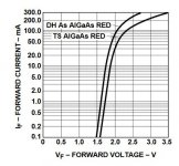
You could try an older type red LED (AlGaAs) with suitable current capacity e.g. a Broadcom HLMP-C115. These have quite low effective impedance (forward voltage / forward current curve attached). You could use 3 or 4 in series then adjust the EL84 screen voltage until you get the current you want (this is the technique SY used with his Red Light District). You'd have to make sure the peak current is acceptable for the LED you choose.
You could try an older type red LED (AlGaAs) with suitable current capacity e.g. a Broadcom HLMP-C115. These have quite low effective impedance (forward voltage / forward current curve attached). You could use 3 or 4 in series then adjust the EL84 screen voltage until you get the current you want (this is the technique SY used with his Red Light District). You'd have to make sure the peak current is acceptable for the LED you choose.
Attachments
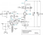
There is an example here, where Pete Millet is using an EL802 to drive a 300B.
Unnecessarily complex 300B amp
schematic
Unnecessarily complex 300B amp
schematic
Attachments
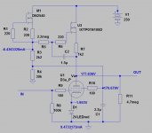
Continuing suggestions from Bass, a little custom great ideas for a pentode driver from Bartola valves.
D3A is here, but it's also very doable for EL84.
BTW, if I remember correctly, Thorsten used SV83 to drive 300B.
And yes, EL84 is superb driver. Cheked !!!
D3A is here, but it's also very doable for EL84.
BTW, if I remember correctly, Thorsten used SV83 to drive 300B.
And yes, EL84 is superb driver. Cheked !!!
Attachments
Hello folks.
has anybody tried LED bias for pentode (e.g.EL84) driving a 300B SET?
I'm currently putting together a monobloc variation of the thorsten Loesch's "Legacy" (albeit more uF and a choke in the prereg stage of the PSU. The PSU caps are all polypropylene, and I'm keen to stay away from electrolytics throughout (Won't be able to lift the things in a few years to replace if I live long enough).
So the question is..... resistor/ cap versus LED cathode bias. Driver stage only.
The Thorsten driver stage utilises cap/resistor but has a very low current of 5.5/470 which suggests only a sinle series of LEDS, or is this biased very low (e.g compared to Morgan Jones red light amps output stages and so on).
Enlightenment/experience/musings (at c.a 650nm wavelength) would be much appreciated.
Ta
Andrew
Why do that? Gary Pimm used EL34 in pentode to drive 300b using a CCS and simple cathode resistor. He got a gain of 125 - so a whopping 90V RMS at only 0.25% THD..... That is pretty darned impressive with a mere degenerated cathode. Only 500 ohm output impedance too, so no problem driving the that (really horrible) 300b.
I wouldn't bother with the LED, but hey... some people like the "light".
Last edited:
Many thanks to all
Thank you knowledgeable people. Some "straight to it insights", especially about the IV characteristics (have done this for a few diff colours of LED over the years (A level Expt for Planck's Constant) and was in a quandary about 1 string of LEDS being lit to bust or a double string being on the gentle bend of conduction.
Still putting the casework together, so I think I will put some redundancy in there and give both bias methods a go as the circuit is built up over the next couple of weeks.
A real shame is my aged lugs and memory being the only judge - oh for a spectrum analyser!
Once again,
Thanks,
Andrew
A real shame is my aged lugs and memory being the only judge - oh for a spectrum analyser!
You can achieve a lot with a halfway decent sound card or USB audio interface along with free REW software which now includes frequency and level sweeps for distortion analysis, as well as real time distortion spectrum.
EL84 is one fine driver. Have some running LTP on a 6CB5A pentode amp. 8k plate loads from a 280V B+, g2 at 105, and idle current of 18 mA. Absolutely brilliant.
Currently in process is a 6AH4 line amp. standard red LED's running as close to 20 mA idle as I can manage. CCS/mu-follower plate loads and bias target of -15V. On ccs-es, the LED's work quite well, avoid the extra bright ones, their curve is not as steep.
cheers,
Douglas
Currently in process is a 6AH4 line amp. standard red LED's running as close to 20 mA idle as I can manage. CCS/mu-follower plate loads and bias target of -15V. On ccs-es, the LED's work quite well, avoid the extra bright ones, their curve is not as steep.
cheers,
Douglas
This is similar to my limited experience of LED bias on DH valve, using anode CCS.
I used mainly Red low current LEDs, but also I have used yellow/amber because the slightly higher Vf gave a slightly higher bias voltage, which acted the same as 3 red LEDs in series plus one diode drop.
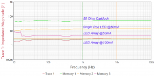
If you look around, the yellow amber have a slightly steeper Vf curve than the red, often touted as being best due to lowest dynamic resistance/noise. (Morgan Jones "Valve Amplifiers")
I used mainly Red low current LEDs, but also I have used yellow/amber because the slightly higher Vf gave a slightly higher bias voltage, which acted the same as 3 red LEDs in series plus one diode drop.
If you look around, the yellow amber have a slightly steeper Vf curve than the red, often touted as being best due to lowest dynamic resistance/noise. (Morgan Jones "Valve Amplifiers")
If you do a search for "Red light district" amp you'll see lots of info for using LEDs to bias a power stage. If you parallel a few using Red LED you can get great results.
The Red Light District - another PP EL84 amp
The Red Light District - another PP EL84 amp
Hello,
you can put an LTZ-MR15 diode instead of a led instead! These are special regulating diodes designed for.
you can put an LTZ-MR15 diode instead of a led instead! These are special regulating diodes designed for.
Done it, built and ear tested. The full saga
Hi folks, gave it a go. The joys of lockdown!
I thought it would be good to round off this thread. The whole 300B thing has been about 16 years in the making. Amplifiers were built as monobocs using parts I had mainly accumulated BC (before children) and a few more recent bits (1200VSiC diodes….when did they arrive? DC link PP caps, I really have been Rip van Winkling). Chassis were made from 3mm Al sheet, U channel ends and box channel sides (with the heater supplies neatly running down them). Most wiring is Ag/Cu/PTFE solid core. With the exception of the 300B filament supply filtering, all caps were polypropylene. The power supply smoothing and regulation used an etched circuit board, but this was mainly used as a convenient way to securely mount the blocky MKP capacitors. The tip of the iceberg amplifier section was point to point wired.
Power supply:
Transformers and 5H, 250mA chokes from Solartron oscilloscopes (same model, one set by ”Gresham” , the other by “Parmeko”. Both tested identically for resistances and off load voltages). The ratings are total overkill, but I’ve been hording them for several years
Rectification. Originally I was going to use GZ34, but I then had a change of mind. Several variations of design were plugged into PSU designer and came up as potentially damaging to GZ34s the others being marginal. At whatever they cost these days, I didn’t fancy shelling out for any pops.
I started with stacked 1N5408 diodes (on hand) whilst “testing” and waiting on 1200V Schottky SiC diodes (SCS205KGC) to arrive, thus safely being within the x2 voltage requirement). In the initial 1N5408 version my oscilloscope clearly showed switching spikes form the diode/transformer so the transformer secondary coils were snubbed using a [ C ||(R+C) ] combination. The values were determined by estimating the transformer leakage inductances (see Haggerman “Calculating optimum snubbers”). With the primary coils shorted the secondary was used to make a resonant circuit with a “large” film capacitor (i.e assumed to be far greater than the secondary interwinding capacitance) and performing a frequency sweep. With the snubbers (values [ 0.022uF || (120+ 0.1uF) ]) installed at the transformer outputs, switching spikes were no longer observed.
Pre-regulator filtering was a legacy of the original GZ34 plan, simply a C-L-C filter (40uF- 5H-3*40uF). Capacitors were Epcos DC link.
Regulation was directly copied from Thorsten Loesch’s original version and utilised one 6080 pass valve per amplifier.
Post regulator filtering utilised a huge 440uF 1100V Electronic Concepts polypropylene capacitor.
Any ripple in the final B+ was below the sensitivity of my ancient oscilloscope, so I couldn’t “optimise” using the Hum Buck pot. That will be looked into after “lockdown” is lifted. There is absolutely no noise detectable at the speakers (Lowther Acoustas + 16Ohm PM6a units).
Amplifier circuit
Again, directly copied from Thorsten Loesch’s original version using an El84 driver stage. B+ was adjusted to 420V.
This is where I return to the original thread….. I started out using a Silmic cap and resistor for the el84 bias. After a fortnight of listening and being stuck at home I decided to give the LED bias method a go. Using some cheap red LEDs, Everlight 2873831404, (a la Morgan Jones). The LEDS I-V characteristics were tested over 1-10mA, at 10mA the resistance gradient was 46 with a voltage drop of 1.8V. Upon installation of a string of 3 LEDs the cathode biases in the amplifiers was 5.83 and 5.90V, suggesting a current 0f 10-15mA (further testing required to narrow this down, save that for another day), but quite similar to the 12mA of the cap/resistor bias).
The output transformers are James 6123HS, set for 2.5k input and 16 output.
Listening tests
Before I go on, I should mention that I’m 54 and the ears have been subjected to quite a lot of sonic abuse over the past 40 years or so. So onto subjectivity and false memories….Valve line ups have been permutations of Mullard and Golden Dragon El84s, and Electro-Hamonix and Billington Gold (Chinese) 300Bs.
I was quite pleased with the original cap||resistor El84 bias. The sound was quite different to the ECC88 triode modded Quad IIs (see ~ QUAD II Valve Power Amplifier triode cascode phase splitter driver ~) I have been used to. They certainly seemed clearer in the upper mids, but the bass (yes I know, Acoustas….) wasn’t quite there compared to the push pull amplifiers.
Upon changing to the LED bias, there was a very definite change for the better. I’ve been listening to much the same stuff for many years and all I can say is that I can now follow individual instruments more easily and I have heard low level detail that is new to me. The bass region seems to have also improved and there seems to be more attack to bass lines and kick drums when they are there. Stereo imaging seems to be better, and some smarty pants panning effects are more evident. Some albums still sound awful.
Without measurement, whether I’ve made a harmonic generator effects box or not, I can only say that I am very pleased with the final (for a while…) sound, especially with the LED bias in place. The red light emanating from the ventilation holes is worth a smirk. Sadly the W/Kg number is vanishingly small. Ho (no) hum.
The LEDS I-V characteristics were tested over 1-10mA, at 10mA the resistance gradient was 46 with a voltage drop of 1.8V. Upon installation of a string of 3 LEDs the cathode biases in the amplifiers was 5.83 and 5.90V, suggesting a current 0f 10-15mA (further testing required to narrow this down, save that for another day), but quite similar to the 12mA of the cap/resistor bias).
Since the voltage drop across a diode is normally pretty stable within the diode's normal current operating range, how can you know what cathode current you have? I don't know of a way to estimate the current unless you know the instantanious resistance through the string plus whatever limiting resistor is in series which depends on the supply voltage which you cannot know since the diode is a variable resistor of sorts, acting as a zener might. If your diodes are just over the turn-on voltage to get them lit, then what happens with the signal on the cathode as it swings? Does it clip the LED's so fast you can't see it without a scope? Did you test the output at full power? If you want a good estimate of the EL84 current, pull the tube and measure the plate load resistor as accurately as you can then use the voltage drop calculation across it instead of using a cathode resistor.
testing
What I intend to do (as soon as I can bend my back over a soldering iron)
is to to put a string of 3 together, adjust voltage drops 5.5 to 6.0V and measure current and see how it looks. Not in situ, I know but I really hate sticking probes into a live rats nest and with the dodgy back, I doubt if I could lift teh blessed things off the shelf.
Since the voltage drop across a diode is normally pretty stable within the diode's normal current operating range, how can you know what cathode current you have?
Just add a 10R resistor in series with the LED string, at the ground end, and measure mV across it.
Just add a 10R resistor in series with the LED string, at the ground end, and measure mV across it.
Yes... It was a rhetorical question based on three series diodes and nothing else. No current limiter. What calculation can be used for this diode biasing? .... It's not a simple cathode resistor test point voltage and resistance formula when using diodes. The plate voltage will set the current through the tube. So how do you predict the idle current when all you have is a cathode voltage but no known resistance. Is a plate chart all you need? What does signal on the cathode do to the bias point?
I did wonder if it was a 'serious' question - excuse me if I sounded patronising, it wasnt my intent.
Moving on to your question, if you know the cathode to grid voltage, say 5.8V for 3 series low current LED, then draw your loadline and trace it across at your bias point, using your measured anode voltage at idle with no signal. That will give you your cathode current.
If I have missed the premise of your question again, sorry - feeling brain dead today.
One thing I have noticed with LED bias of power stages is that at VLF, say 20Hz and lower the LEDs visibly flicker at high output.
Whether this is simply persistence of vision at work, and the LEDs always flicker, or something else, I dont know.
I guess it would be cathode AC current swings at large outputs, serving to partially overcome the DC bias current, and extinguish the LED.
Again, if that's a problem. I dont know.
I have noticed that LED bias generally gives me slightly higher gain that bypassed cathode resistor, a marginal increase.
On occasion too, I have noticed that the 3rd harmonic is, marginally, ever so slightly, worse than a simple bypassed resistor - again this is only anecdotal and probably depends on many other variables, biasing, harmonic cancellation between stages, etc.
- Home
- Amplifiers
- Tubes / Valves
- LED bias for pentode driven 300B SET