Here ow the new "Measuring LDO with passive/active notches/filter", so that we no longer hijacking the "Low-distortion Audio-range Oscillator" thread.
Administrator please move last related to this one..
In other words the measure a LDO with passive components or using active components as with OPAMP's provides several challenges in terms of
. Notch Depth
. THD & Noise added given from the parts (R/C/OPAMP's)
. Noise alternations (reduced or amplified) in any form
. Harmonic's attenuation
. May consider balanced or none balanced use
..
Hp
Last edited:
You might want to ask the admins to spell out LDO as "Low distortion oscillator" as the typical use of the acronym is for "low dropout" in terms of regulators. I was confused when I clicked on your title, fyi. 🙂
Controlled notch depth
We often speak here of obtaining extremely deep notches, and meeting that challenge is always a good thing. However, in one of the main applications we are discussing, namely removing the fundamental to allow subsequent distortion analysis instruments to have a higher effective dynamic range and look down to lower harmonic levels, we do not necessarily need extremely deep notch depth to greatly enhance overall measurement capability. For example, if our measurement instrument can see down to -110 dB in normal operation, even a 40 dB notch gets it down to the -150 dB range, assuming no distortion contribution from the notch.
In fact, a more desirable approach in many instances would be a very good notch, but with an accurate and controlled depth. This would allow an accurate fundamental amplitude marker to be placed on the FFT. In other words, bypass a little bit of the notch to allow maybe -40 dB of feedthrough of the fundamental. This would give a sanity check in evaluating the actual amplitudes of the harmonics. I do this for the same reason in my Distortion Magnifier. This small amount of fundamental feedthrough can also often be used to provide a subsequent THD analyzer to lock onto the fundamental and perform its auto-tuning. If we have a 60 dB notch and bypass it with a -40 dB fundamental, we will get about 10% accuracy on the fundamental amplitude marker, which is only 1 dB of error - not a big deal when measuring distortion in the -130 to -150 dB neighborhood.
Cheers,
Bob
In other words, bypass a little bit of the notch to allow maybe -40 dB of feedthrough of the fundamental.
Is there a way to set a constant notch depth, regardless of what the actual maximum notch depth is? Say my notch is at 80dB down and then drifts a little upward to only 60dB. Now I want only 40dB total depth at the output, so I'd have to adjust the feedthrough from 40dB (80 to 40) to 20dB (60 to 40). Is there such a thing as a "notch depth servo"?
You are right, I get it right only because I was in my favourite topic about low distortion oscillator. But for a beginners or for google search I'm not sure it is well understood.You might want to ask the admins to spell out LDO as "Low distortion oscillator" as the typical use of the acronym is for "low dropout" in terms of regulators. I was confused when I clicked on your title, fyi. 🙂
Here is the link to the full article about the Hall network I mentioned previously:
http://www.kennethkuhn.com/electronics/design_and_applications_of_the_hall_network.pdf
Regrads,
Braca
http://www.kennethkuhn.com/electronics/design_and_applications_of_the_hall_network.pdf
Regrads,
Braca
Here is the link to the full article about the Hall network I mentioned previously:
This is exactly what is called the "Bridged Differentiator" in "The Art Of Electronics".
Looks like this topology could be perfectly suited to what we're after. With two pots you can center the null and adjust its depth! Dammit, I'll have to build one now.
EDIT: Adjusting the notch depth with one pot influences the center frequency set with the other. The opposite is also true, but the notch depth varies only very slight when setting the center frequency. This looks like it would be easily manageable in real life.
Last edited:
Yes, you're right with your analysis.
You only have to adjust the middle frequency once with a trimmer pot in the series resistor line, and then solder a fixed one instead.
I've built two such filters - one fixed, and one adjustable.
The PCB was designed by Samuel Groner several years ago, and there was a GB for it on this forum:
PCB for Samuel Groner's low distortion passive notch filter
The thread has been dormant for more than a year. You can see the results of my measurements on this filter at the end of the thread.
Regards,
Braca
Yes, you're right with your analysis.
You only have to adjust the middle frequency once with a trimmer pot in the series resistor line, and then solder a fixed one instead.
What do you do if the oscillator frequency drifts a little over time or warmup? You'd have no means to correct for this. Or is the notch wide enough to account for this?
Samuel obviously uses a passive filter to avoid the added distortion of the bootstrap circuitry. Does anyone know of a direct comparison between the active and passive versions of a notch filter, be it a Hall network or a Twin-T?
I was writing about a one-time adjustment of the center frequency. Referring to Fig. 6 in Kuhn's write-up, it is the trimmer R4. It is used only once, to adjust the filter for the deepest notch at the nominal frequency of the oscillator. In my case it is about 998Hz. To minimize the distortion, the trimmer is then replaced by a fixed resistor.
The trimmer (or potentiometer) RP is used to adjust the notch every time you use the filter to measure THD. In my case, it is a 10-turn trimmer with an axial adjustment screw. My typical THD measurement run takes 5 to 10 minutes, and if the oscillator has been stabilized beforehand, the notch depth does not change much.
For THD measurements, the notch does not have to be extremely deep - everything below -40dB is ample.
After the filter, I have a 60dB LNA (Groner or Wurcer) in my setup, and then the audio interface.
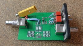
Attached below is my adjustable filter before closing the case. Samuel's PCB is meant for a fixed frequency filter so I modified it at a few locations with a scalpel in order to realize a variable frequency one.
Regards,
Braca
The trimmer (or potentiometer) RP is used to adjust the notch every time you use the filter to measure THD. In my case, it is a 10-turn trimmer with an axial adjustment screw. My typical THD measurement run takes 5 to 10 minutes, and if the oscillator has been stabilized beforehand, the notch depth does not change much.
For THD measurements, the notch does not have to be extremely deep - everything below -40dB is ample.
After the filter, I have a 60dB LNA (Groner or Wurcer) in my setup, and then the audio interface.
Attached below is my adjustable filter before closing the case. Samuel's PCB is meant for a fixed frequency filter so I modified it at a few locations with a scalpel in order to realize a variable frequency one.
Regards,
Braca
Attachments
You are right, I get it right only because I was in my favourite topic about low distortion oscillator. But for a beginners or for google search I'm not sure it is well understood.
How about LTHDO (or Low THD Osc) instead of LDO? THD should be more recognizable, and not unduly increase the length of the thread title.
Is there a way to set a constant notch depth, regardless of what the actual maximum notch depth is? Say my notch is at 80dB down and then drifts a little upward to only 60dB. Now I want only 40dB total depth at the output, so I'd have to adjust the feedthrough from 40dB (80 to 40) to 20dB (60 to 40). Is there such a thing as a "notch depth servo"?
The way to do it is to just create a bypass path with, say, -40 dB of attenuation, summing that with the output of the notch with an op amp. As long as the notch itself is at least 20 dB deeper than the desired depth, the ultimate notch depth will be reasonably close to 40 dB. The ultimate notch depth can be controlled by how much attenuation you put in the bypass path.
Cheers,
Bob
It is better.How about LTHDO (or Low THD Osc) instead of LDO? THD should be more recognizable, and not unduly increase the length of the thread title.
I was thinking along the lines of a notch depth that's not conveniently constant, but fluctuating a little (20dB was an extreme example). Instead of adjusting the bypass, I might just as well adjust the notch depth itself, or am I missing something here?
As it turns out, my cheap 60'000 counts multimeter is not up to snuff to match some passives with enough accurracy. For a 16k resistor I can only get 10 Ohm resolution, that's just not doing it 🙁.
I put everything together nonetheless and did a first test. The notch frequency is about 5Hz lower than what the simulation predicted when fed with the actual values that I measured, and the notch depth doesn't get any better than 50dB. Pretty disappointing for all that parts involved... I'll do some more tweaking the next days, but I'm done for today.
.. but I'm done for today.
May consider doing some noise analysis as on YouTube shown.
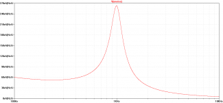
While my active T-notch (as the topologie shows 2 Opamp's in a Loop) a rising noise bell, as Oszillation happen around the 1kHz … will post soon some details about.
Here again once more... I love here the noise figures seen at https://www.edn.com/three-op-amp-state-variable-filter-perfects-the-notch/
BTW: For me, the active tracking filter (looks like a notch) on the AP-2722 similar as above, showing a similar filtering responce.
Here you go. No comparison to the State Variable Sim you linked to.
Yeah 😱
Here some about the AP patent and from 2004 on this forum:
Circuits / Info on Tracking Notch Filters
US Patent for Dual-stage filter with feedback Patent (Patent # 4,563,652 issued January 7, 1986) - Justia Patents Search
Now an AP-2272 filter measurement, KEEP IN MIND the -120 dB filter deep is limited to the used setup
But shows much about the filter curve..
Hp
Attachments
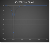
But shows much about the filter curve..
Neat! No need for accurate tuning, just make the notch wide enough to account for some Hz give or take.
- Home
- Design & Build
- Equipment & Tools
- Measuring LDO with passive/active notches/filter