Ahoy,
I'm in the final stages of restoring this having made a new switch and repaired a main board crack and the aftermath of a small fire among many other things.
With the unit on, nothing in circuit except the output ICs, and volume on minimum there is significant hiss in the headphones.
As a transistor neophyte, feeling my way, I wondered if anyone had any suggestions as to where the constant output stage noise is coming from and what I could do to mitigate it in an existing circuit.
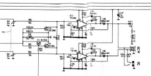
Attached is the diagram - the previous IC and all other boards are removed so there is no input. If I ground the input pins of each channel, there is a buzz somewhere between motorboating and mains hum.
I notice the datasheet of the op-amp contains more capacitance on the power line. I think this could be a culprit, as if the motor is engaged (with no connection between the heads and the output) there is hum added to the hiss. While the diagram says C37 is a 1µF/35V, the tantalum capacitor in circuit was 0.1µF (I replaced it with polyester).
There is 4.6VDC on the output, reduced to 3mV after the coupling capacitors.
I'm in the final stages of restoring this having made a new switch and repaired a main board crack and the aftermath of a small fire among many other things.
With the unit on, nothing in circuit except the output ICs, and volume on minimum there is significant hiss in the headphones.
As a transistor neophyte, feeling my way, I wondered if anyone had any suggestions as to where the constant output stage noise is coming from and what I could do to mitigate it in an existing circuit.
Attached is the diagram - the previous IC and all other boards are removed so there is no input. If I ground the input pins of each channel, there is a buzz somewhere between motorboating and mains hum.
I notice the datasheet of the op-amp contains more capacitance on the power line. I think this could be a culprit, as if the motor is engaged (with no connection between the heads and the output) there is hum added to the hiss. While the diagram says C37 is a 1µF/35V, the tantalum capacitor in circuit was 0.1µF (I replaced it with polyester).
There is 4.6VDC on the output, reduced to 3mV after the coupling capacitors.
Attachments
I'd use ceramic for that 0.1µF decoupler so it works at RF. I'd add lots more electrolytic decoupling, the TDA820 has very poor PSRR. Its also pretty noisy, but for a cassette deck you probably don't care about that.
That's interesting, Mark. Perhaps there wasn't a better chip available in 1979!
Reading up on today's offerings, I see that 100dB PSRR is the norm, whereas the TBA820 has 40dB! Perhaps I could fit a more modern 14-pin example in its place?
The rail comes from the PSU with no decoupling in between except that 0.1µF I took out (having read about the problems of tantalum decouplers), so it can't be helping. I'm limited by space in the chassis as the loudspeaker sits just above the TBA820s when the thing's screwed together, but I can certainly fit the datasheet's suggested 1µF and the ceramic.
Is the hiss in this case then simply the various noises of the component itself? I'll see if it changes when the RF is reduced.
Through the loudspeaker it's not noticeable for monitoring, and I've not tried the output to an external amplifier yet. It's just very obvious in the headphones, which for a high-end 'professional' machine of the day isn't so hot for recording.
I could try reducing the gain as well - they're plenty loud enough at very low volumes.
I think your problem is twofold:
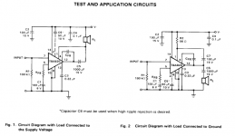
1. Mediocre PSRR as suggested capacitor C6 (Fig. 2) is not installed.
2. Almost no attenuation for the headphone output, combined with an IC sporting 3 µV of input voltage noise at a gain of 36 dB (output noise ~185 µV - an average-performing headphone amplifier will exhibit 20-30 µV, a good one <2 µV).
ICs like the TBA820 were a common sight e.g. in clock radios of the time. In this device it may have been chosen for its low power consumption.
The easiest way of taming the headphone output (short of using an external attenuator) would be changing the values of R74/75 and adding two more from each output to ground (a good low-impedance ground return), so that a practical attenuation of maybe 16-20 dB would be achieved. What kind of impedance and sensitivity are your headphones? For sensitive 32 ohm cans I might use 120 ohms followed by 12 ohms, for typical 250-300 ohm Beyerheisers more like 330-390 ohms and 47 ohms, and for only moderately sensitive old 600 ohm jobs perhaps 330 ohms and 100 ohms.
Adding a little dedicated headphone amplifier board suitable for single supply operation may be another option, though this may be hard to fit into such a compact device.
Thank you for the thoughts.
I thought this was strange too, comparing the diagrams. I can't think why the designers didn't want to get the best monitoring output they could, which would surely include reducing ripple. Perhaps mains power was considered less common than battery. I will mainly be using it on the mains.
That could be the case - as it is, I understand from the specifications that it isn't easy on batteries! I haven't found a modern drop-in replacement from my usual suppliers, so I think I'll work with this and the noise-reduction ideas in the interests of DIY, originality and cost.
Interesting - I have both ends of the spectrum there, but more likely to use the 32 Ohm for listening at home. Is the intention to create a voltage divider for permanent attenuation? Am I right in deducing that at present the resistors are just there for approximate impedance matching for 32 Ohm headphones?
I think your problem is twofold:
1. Mediocre PSRR as suggested capacitor C6 (Fig. 2) is not installed.
I thought this was strange too, comparing the diagrams. I can't think why the designers didn't want to get the best monitoring output they could, which would surely include reducing ripple. Perhaps mains power was considered less common than battery. I will mainly be using it on the mains.
2. Almost no attenuation for the headphone output, combined with an IC sporting 3 µV of input voltage noise at a gain of 36 dB (output noise ~185 µV - an average-performing headphone amplifier will exhibit 20-30 µV, a good one <2 µV).
ICs like the TBA820 were a common sight e.g. in clock radios of the time. In this device it may have been chosen for its low power consumption.
That could be the case - as it is, I understand from the specifications that it isn't easy on batteries! I haven't found a modern drop-in replacement from my usual suppliers, so I think I'll work with this and the noise-reduction ideas in the interests of DIY, originality and cost.
The easiest way of taming the headphone output (short of using an external attenuator) would be changing the values of R74/75 and adding two more from each output to ground (a good low-impedance ground return), so that a practical attenuation of maybe 16-20 dB would be achieved. What kind of impedance and sensitivity are your headphones? For sensitive 32 ohm cans I might use 120 ohms followed by 12 ohms, for typical 250-300 ohm Beyerheisers more like 330-390 ohms and 47 ohms, and for only moderately sensitive old 600 ohm jobs perhaps 330 ohms and 100 ohms.
Adding a little dedicated headphone amplifier board suitable for single supply operation may be another option, though this may be hard to fit into such a compact device.
Interesting - I have both ends of the spectrum there, but more likely to use the 32 Ohm for listening at home. Is the intention to create a voltage divider for permanent attenuation? Am I right in deducing that at present the resistors are just there for approximate impedance matching for 32 Ohm headphones?
Indeed. You want to find a good compromise between output impedance and noise / remaining maximum output level. To complicate matters, sensitivity to output impedance varies quite a bit between headphones even at same nominal impedance - you can do the math if you have an impedance response for the model in question. (A handful of models like a few old Beyers actually sound best at a non-zero output impedance.) Likewise, sensitivity also varies a fair bit.Interesting - I have both ends of the spectrum there, but more likely to use the 32 Ohm for listening at home. Is the intention to create a voltage divider for permanent attenuation?
Your guess is as good as mine. Headphones were at least as much of a mess in 1977 as they are now. I would like to think that the developers' cans of choice may have been the trusty 2 kOhm Sennheiser HD414 or HD424 (the 600 ohm versions only came out in the very late '70s I think) rather than their 8-25 ohm Japanese counterparts, but who knows. As-is, the output is inadequate for almost anything I can think of.Am I right in deducing that at present the resistors are just there for approximate impedance matching for 32 Ohm headphones?
I now have a new copy of the manual (it seems these and the leatherette cases are both available new from the service place I ordered them from in Germany), and the technical specification says:
"Headphones Output: max. 2V per channel (for headphones of 8 to 12kohms). I imagine that means 8 ohms to 12kohms (what kind of cans are they!?) rather than 8kohms to 12 kohms.
The 'outputs' section says that the headphone jack is 'for connecting low impedance stereo headphones'; while the headphones/loudspeaker output is 'for connecting stereo headphones that are equipped with a 5-pin DIN plug (e.g. UHER W 765 and W 775) requires using UHER Adapter K 633, the lead which must also be used to connect two loudspeakers (impedance 4 ohms) or self-energised speakers.'
I think something got lost in translation there.
Charmingly, the instructions are divided into 'For Users in a Hurry' and 'For Enthusiastic Audiophiles'.
I assume the service place you mention is SDS?
SDS UHER Service
Ulrich is very knowledgable and can turn up some interesting bits and pieces. I recently bought a new old stock power supply for my CR210.
SDS UHER Service
Ulrich is very knowledgable and can turn up some interesting bits and pieces. I recently bought a new old stock power supply for my CR210.
Yes, that's the chap! Some years ago I bought the small plastic catch for a 4000 Report-L from Johann Gruber, another Uher service fellow, but the money transfer was awkward and ended up costing more than the item!
Thank you for all the help. Finally after Christmas I've got onto this and the result is that the headphone experience is much improved. The speaker output is attenuated too, but it sounds good. It's probably confirmation bias, but I was very impressed listening to it when I'd finished. The photograph shows the new resistors in place on the headphone outputs.
Now there's just some crackle occasionally from the Dolby board, which I haven't yet touched. It's either the tantalums or a dodgy connection from the board edge sockets.
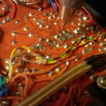
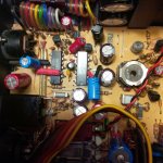
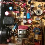
I was quite pleased how I managed to fit in the extra capacitors for the TBA820. In the pictures attached you can see I've got them away from the ICs themselves, as that is where the back of the loudspeaker sits and there's very little room above them. In fact, I think that's why there was a fire on the board, because a previous repair had allowed the 'speaker to push the previously cracked motherboard down until the solder side touched the casing. The two blue ones are "C6"; the yellow ceramic bypasses the black for RF in the centre; and the larger black one at the top right decouples the power supply which helpfully happens to be bridged to the component side at that point.
I drilled out some of the holes to allow two component legs through them - a couple of the IC pins required were unused so the legs were just in un-padded holes in the board. At the bottom of the drill photo, all those orange wires are jumpers I had to put over all the traces that were cracked when I first bought the machine...
Now there's just some crackle occasionally from the Dolby board, which I haven't yet touched. It's either the tantalums or a dodgy connection from the board edge sockets.
I was quite pleased how I managed to fit in the extra capacitors for the TBA820. In the pictures attached you can see I've got them away from the ICs themselves, as that is where the back of the loudspeaker sits and there's very little room above them. In fact, I think that's why there was a fire on the board, because a previous repair had allowed the 'speaker to push the previously cracked motherboard down until the solder side touched the casing. The two blue ones are "C6"; the yellow ceramic bypasses the black for RF in the centre; and the larger black one at the top right decouples the power supply which helpfully happens to be bridged to the component side at that point.
I drilled out some of the holes to allow two component legs through them - a couple of the IC pins required were unused so the legs were just in un-padded holes in the board. At the bottom of the drill photo, all those orange wires are jumpers I had to put over all the traces that were cracked when I first bought the machine...
Attachments
Excellent work. This under-appreciated cassette recorders are well-worth maintaining, especially if you are into field recording. Digital recorders are lighter and higher quality but don't have the romance, somehow.
Thank you for the kind words, Colin. This machine has really been a labour of love since I got it in 2018. It came to me in a Uher Miniline set delivered via a friend in Germany as the seller wouldn't post to the UK. As mentioned, the motherboard was snapped and one of the cast case lugs which hold the bottom screws was snapped off. Araldite and jumpers carefully soldered cured that.
I hadn't used an oscilloscope before, so experimented with help from the vintage-radio UK forum and managed to learn to trace signals and interpret transistors, having only had valve experience before. The new circuit diagrams I had from SDS were a real boon as before I'd been working from the only PDF available online which was pretty low resolution, and for an earlier model with component differences.
Then there were problems with the recording signal and the record switch snapped. See photo. Unfortunately I can't find my photos of the new switch...I made a new switch from carefully copying the original onto tracing paper and making an etching templet (using callipers to measure the contact distances), which I used to etch two pieces of copper-clad board. I had some double-sided board which I had to file down to two thin pieces of single-sided which I Araldited together. I then etched a rudimentary contact shape on each side with permanent marker resist, then tidied it up with needle files while testing each contact on the switch in the two positions. I then glued in the latch from the old switch (I had to file a cavity between the two halves of the new switch) and glued on the knob. Despite all my measurements, the knob is a little proud. I'm calling that patina and aged character!
I've replaced most of the electrolytics on the motherboard, and found a dodgy tantalum on the pre-amp board. This has now had most of its tantalums replaced with mini-electrolytics and performs much better.
I dismantled the motor and checked its lubrication and connections, re-doing its foam vibration-damping on reassembly.
The real annoyance is the plugs and sockets which are all wired with very thin solid-core which snaps at the least work-hardening. If I were of a stronger disposition I would replace the loom with flexible wire.
I also replaced the electrolytic in the power supply which sits in the battery compartment (Z131?) and had to do a deal of work with the PSU board which had some broken contacts.
I just recorded some Marvin Gaye from LP this evening, and even on an old Fe tape it really sounds the bee's knees on Dolby. I was reading G. A. Briggs's 'Stereo Handbook' of 1960 the other week, and he demonstrates the inability of people to hear differences with various equipment of the period, among examinations of the advantages of mono and stereo recordings. I think that the arguments of today really pale into insignificance with the research of that era. When people are arguing over deci-percentage points of distortion, they're listening to components, not the music.
Really, if the music is grabbing you then the equipment is top notch, whatever it is - I often find a blues 78 in a field on a wind-up to be superior in presence to an SACD with a multi-mic setup just from the atmosphere! In that sense, the romance of the cassette, the electro-mechanical engagement with the recording instrument and (in this case) the personal effort that's gone into the repair and recuperation, means that of course it's going to sound wonderful and be a joy to use!
I plan to use the Uher for field recording, as well as recording from my other pieces of obsolete equipment. Lanois production, here we come!
Attachments


That doesn't sound right, unless you also reduced the gain. What exactly did you end up changing in the circuit aside from the capacitors?Thank you for all the help. Finally after Christmas I've got onto this and the result is that the headphone experience is much improved. The speaker output is attenuated too, but it sounds good.
Really, if the music is grabbing you then the equipment is top notch, whatever it is - I often find a blues 78 in a field on a wind-up to be superior in presence to an SACD with a multi-mic setup just from the atmosphere! In that sense, the romance of the cassette, the electro-mechanical engagement with the recording instrument and (in this case) the personal effort that's gone into the repair and recuperation, means that of course it's going to sound wonderful and be a joy to use!
I plan to use the Uher for field recording, as well as recording from my other pieces of obsolete equipment. Lanois production, here we come!
I completely agree and have also enjoyed music on 78s more than LP at times.
What sort of field recording are you planning on doing? I found the key was to use good mics, especially with older equipment such as the Uher.
That doesn't sound right, unless you also reduced the gain. What exactly did you end up changing in the circuit aside from the capacitors?
I realised once I'd put it back together that I'd taken the potential divider from the same position rather than the headphone ground, i.e. the new resistor to ground is in parallel with the socket, with the output and both resistors meeting electrically at the same point.
Thus, with the speaker switched in, the output is still coupled to ground without headphones plugged in!
The DIN headphone out has no resistors in the original. I wonder why.
I am not sure I follow what you are saying. Each output should be seeing (R74/75 + added Rx) in parallel to the speaker, only adding some negligible extra loading.I realised once I'd put it back together that I'd taken the potential divider from the same position rather than the headphone ground, i.e. the new resistor to ground is in parallel with the socket, with the output and both resistors meeting electrically at the same point.
Thus, with the speaker switched in, the output is still coupled to ground without headphones plugged in!
Could you try drawing what you did into the schematic, just to see whether we agree on what is present vs. what should be?
External speaker connection, I think.The DIN headphone out has no resistors in the original. I wonder why.
BTW, these DIN headphone jacks have one neat trick up their sleeve: Turn the plug by 180°, and you can choose between muted or non-muted speaker.
Last edited:
It's almost a year, but I'm still here...
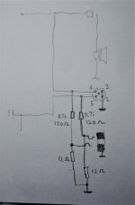
I've got the Uher apart again and finally made the sketch. Funny old year, eh?
This is what I've got inside. You see the loudspeaker is always going to be coupled to ground when switched on.
I got the machine out to make some recordings and the speed control was all over the place. I've decided the pinch roller is most likely to blame so have a new one on the way. Not cheap, but if it works...
Attachments
Is that 5 pin DIN headphone socket indeed wired directly to the output stages? That would be quite unusual 🙄.
Best regards!
Best regards!
Yes, see the original circuit diagram in post #1 - the loudspeaker is switched, but the headphone jack and DIN socket are on the same lines and always on.
- Home
- Source & Line
- Analogue Source
- Uher CR240 hiss in output stage/general noise reduction