An inductor will act as a high impedance to AC but a low impedance to DC, in other words if you slap an inductor onto the plate of a tube or something, the tube's bias will determine the current through the inductor.
Since an inductor doesn't set the idle curren't it doesn't set the idle plate voltage, unlike a current source where the plate voltage must be determined by the current set by the current source due to ohms law.
A gyrator as I'm assuming we're talking about, is an electronic inductor. It can't swing beyond the rails like an inductor, but it will present a high impedance to AC without affecting the idle current.
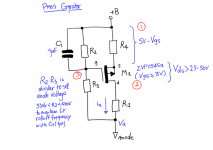
Really? Talking about the two circuits I posted: the mosfet set a crude but real voltage reference, then the two resistors attached to the gate, which make a voltage divider, can be used to vary the anode voltage. Am I wrong?
Sorry didn't see you're post.
You're mostfets are Pcan with a fixed voltage on the gate and the high impedance end facing the load so it will function as a current source, not a gyrator in that configuration.
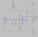
If you want to make a gyrator with the same complexity of your circuits you want something like this

The current source ensures a stable voltage across the R3
The mosfet is a source follower so it sets the voltage and the capacitor allows AC feedback to create a high impedance at AC.
You can take the output at either side of R4 depending on how much you want to load the triode or whatever your connecting and whether or not you want the signal current to enter the power supply.
Taking it above the resistor keeps a constant current on the load and lets the mosfet drive the next stage. Taking it below the resistor removes the constant current from the load but ensures the signal current does not enter the power supply.
Bartola and Rod Coleman makes PCBs for this type of circuit that perform about as well as can be expected without throwing an opamp in there.
Last edited:
Not being knowledgeable enough to analyze the circuit I have to ask in what way it acts like an inductor. Rising impedance with frequency? Swing above supply voltage?
Thanks
Not sure. That's precisely the reason why I started this post.
I surely doesn't swing above supply (no gyrator does, AFAIK).
They seem to have a rising impedance with frequency, and act as inductive reactance (current lags voltage), in a range of frequencies.
You're mostfets are Pcan with a fixed voltage on the gate and the high impedance end facing the load so it will function as a current source, not a gyrator in that configuration.
If you want to make a gyrator with the same complexity of your circuits you want something like this
...
Bartola and Rod Coleman makes PCBs for this type of circuit that perform about as well as can be expected without throwing an opamp in there.
Thank you. I knew those circuits too. In fact, Bartola website shows a PMOS gyrator like the simple one I posted, and Ale (author) even posted it in this forum as a gyrator. Attached. The other one I posted is based on Salas and Anatoly's (Wavebourn) design . They are people who seem to know what they are talking about. So, I'm jus trying to put all the pieces together and understand by myself.
Attachments
Oh haha, I guess I am blind afterall, yeah that's a gyrator, I totally was not paying attention to where the divider was feeding.
The resistor divider + capacitor combined with R4 allows for AC feedback from the output to ensure that the VGS voltage is the same at AC so the AC current doesn't change. Think of R4 as a resistor load for a source follower, it will try to keep the VGS voltage equal and an unchanging VGS on a mosfet means a constant current.
Feeding the divider to the output also allows the idle current to be set via the load instead of the gyrator because the load resistance is part of the divider.
But changing the divider should still cause the gyrator to change the idle current somewhat. Seems way too flimsy for my liking but it will work in a pinch.
Last edited:
Oh haha, I guess I am blind afterall, yeah that's a gyrator,
But that gets us back to the first post.
In #9 (Gyrator impedance vs frequency) the simulation shows that it only acts as an inductor at very low frequencies, where the impedance is reactive.
See the top (magenta) trace. The phase is just close to 90º (voltage leads current) for very low frequencies. Then, it acts as a simple fair CCS, ok for low internal impedance tubes.
The question I was trying to ask in this thread from the very beginning is: is this the way the circuit is supposed to work?
As I've explained the intent of a gyrator for audio purposes is to act as a current source at AC and a voltage source at DC.
To my eyes the magenta circuit is functioning as expected, acting as a high impedance at audio frequencies.
The green circuit was missing the source resistor in the first few posts and it is not optional, the circuit won't function correctly without it for reasons I explained in my last post.
To my eyes the magenta circuit is functioning as expected, acting as a high impedance at audio frequencies.
The green circuit was missing the source resistor in the first few posts and it is not optional, the circuit won't function correctly without it for reasons I explained in my last post.
As I've explained the intent of a gyrator for audio purposes is to act as a current source at AC and a voltage source at DC.
That makes much more sense. Thank you!
Taking it above the resistor it's a bootstrapped mu-follower...no constant current and the value of the resistor gives the gain, so its value is quite high which makes for higher power supply and power loss on that resistor.It' really hilarious that Bartola rebadged it as cascoded gyrator while , Tektronix used bootstrapped followers and the US Navy used valve variations of mu-followers for decades...claiming intellectual rights over these makes US navy laugh in tears...Sorry didn't see you're post.
You're mostfets are Pcan with a fixed voltage on the gate and the high impedance end facing the load so it will function as a current source, not a gyrator in that configuration.
If you want to make a gyrator with the same complexity of your circuits you want something like this
The current source ensures a stable voltage across the R3
The mosfet is a source follower so it sets the voltage and the capacitor allows AC feedback to create a high impedance at AC.
You can take the output at either side of R4 depending on how much you want to load the triode or whatever your connecting and whether or not you want the signal current to enter the power supply.
Taking it above the resistor keeps a constant current on the load and lets the mosfet drive the next stage. Taking it below the resistor removes the constant current from the load but ensures the signal current does not enter the power supply.
Bartola and Rod Coleman makes PCBs for this type of circuit that perform about as well as can be expected without throwing an opamp in there.
Last edited:
Unfair comment, if you read carefully I always stated it’s a hybrid my follower when taken from mu, and a gyrator load if from anode. The reference to gyrator circuit has stuck into everyone’s mind so no point in fighting that back.
No one claims any copyright of a well known and popular circuit
Ale
No one claims any copyright of a well known and popular circuit
Ale

OK.I'm sorry if i got you wrong!Unfair comment, if you read carefully I always stated it’s a hybrid my follower when taken from mu, and a gyrator load if from anode. The reference to gyrator circuit has stuck into everyone’s mind so no point in fighting that back.
No one claims any copyright of a well known and popular circuit
Ale
I like this design and it simulates, but how do you avoid popping the opamps with a large voltage across their terminals? I've attached my simulation - perhaps you can see where I'm going wrong...Enjoy.

I just conjured it it up in a few minutes so not optimized or anything, not tested IRL.
I once made one that simmed terraohms impedance but I'm too lazy to find the file and no one needs that much. This one ends off at 4 megs @ 20k, plenty.
Attachments
- Home
- Amplifiers
- Tubes / Valves
- Gyrator impedance vs frequency