Hello guys,
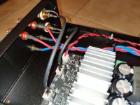
I just finished my build. I'm satisfied by the result, but if I had evaluated the layout better before, the solution would have been much more cleaner and the component distant from each other.
I used coax for line-in and twisted pairs for the speakers, but there's a light hum when i tend over the speakers.
Do you have any suggestion or do I have to live with it?
Attachments


Last edited:
Looks neat.
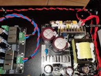
The small EMC filter casing is electrically connected to chassis?
The amplifier board signal ground is electrically connected to chassis?
You have tried to dismount the amplifier board and move it away (upwards on the photo) from the EMC filter?
The small EMC filter casing is electrically connected to chassis?
The amplifier board signal ground is electrically connected to chassis?
You have tried to dismount the amplifier board and move it away (upwards on the photo) from the EMC filter?
Did you try to connect the not used input pins to GND?
The board seems to be with balanced inputs, but you use unbalanced cables.
The board seems to be with balanced inputs, but you use unbalanced cables.
Looks neat.
The small EMC filter casing is electrically connected to chassis?
The amplifier board signal ground is electrically connected to chassis?
You have tried to dismount the amplifier board and move it away (upwards on the photo) from the EMC filter?
Thanks 🙂
The filter casing is grounded so I scratched the chassis and i fixed the filter on it.
The amplifier board is installed on plastic spacers and the line-in too, so the ground is not connected to the chassis. Do you think I should connect the return of the rca connectors to the chassis?
No i didn't move the board. I will try to do it.
Cheers

Did you try to connect the not used input pins to GND?
The board seems to be with balanced inputs, but you use unbalanced cables.
Yes, the board has two jumpers that let you choose single-ended or balanced connections, shorting - and GND.
Cheers
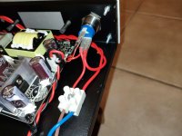
Have you checked that the RCA sockets and Speaker sockets isolated from the case? I have had it where the plastic isolating washers are not deep enough to cover the whole of mounting hole in the case. I wrap insulating tape around the threads and this makes an interference free connection. Use the continuity bleeper on your DMM to check.
Thanks 🙂
.............................................................
The amplifier board is installed on plastic spacers and the line-in too, so the ground is not connected to the chassis. Do you think I should connect the return of the rca connectors to the chassis?
.............................................................
Yes, as Puffin suggests, make sure that the ground of the RCA connectors is connected to chassis. This way the signal ground is connected to chassis.
Have you checked that the RCA sockets and Speaker sockets isolated from the case? I have had it where the plastic isolating washers are not deep enough to cover the whole of mounting hole in the case. I wrap insulating tape around the threads and this makes an interference free connection. Use the continuity bleeper on your DMM to check.
Thanks Puffin, luckily this part was ok 😀
Yes, as Puffin suggests, make sure that the ground of the RCA connectors is connected to chassis. This way the signal ground is connected to chassis.
That was it! The spacer holes are grounded, if I used brass spacers I wouldn't have any problem. I just wired a cable from the chassis to a ground point of the board and the noise disappeared.
It's much more easier than re-soldering the rca, but i'm not sure if I can have any problem this way. What do you think?
You now know the type of solution needed. Grounding at the RCA connectors is in principle the most clean way. What you just did will not cause any harm and if the hum is gone, I would leave it like that.
That was it! The spacer holes are grounded, if I used brass spacers I wouldn't have any problem. I just wired a cable from the chassis to a ground point of the board and the noise disappeared.
I just want to clear something up here. An RCA has a signal and shield connection to the amp board. If the body of the RCA is connecting the chassis it will hum. If the RCA is properly isolated you would not need a wire from the chassis to ground? I have never done this or seen that it it advised to do it.
FauxFrench, did you mean to say make sure the body of the RCA is NOT connected to the chassis which is what I was saying?
Yes, as Puffin suggests, make sure that the ground of the RCA connectors is connected to chassis. This way the signal ground is connected to chassis.
Report Post
Last edited:
That was it! The spacer holes are grounded, if I used brass spacers I wouldn't have any problem. I just wired a cable from the chassis to a ground point of the board and the noise disappeared.
I just want to clear something up here. An RCA has a signal and shield connection to the amp board. If the body of the RCA is connecting the chassis it will hum. If the RCA is properly isolated you would not need a wire from the chassis to ground? I have never done this or seen that it it advised to do it.
FauxFrench, did you mean to say make sure the body of the RCA is NOT connected to the chassis which is what I was saying?
Yes, as Puffin suggests, make sure that the ground of the RCA connectors is connected to chassis. This way the signal ground is connected to chassis.
Report Post
Sorry Puffin if I misunderstood what you wrote.
In my past with class AB amplifiers, we used to connect the amplifier signal ground to chassis. That was often at the outer conductor (signal ground) of the RCA input connectors. As there should only be one connection to chassis in order to avoid ground-loops, that was the single connection point. My impression is that I have seen that on a number of commercial amplifiers as well. The female RCA connectors I have in my lab are made such that they automatically connect electrically to the support. The support is typically part of a metal chassis.
Anyway, my excuses Puffin for citing you for something you did not mean. I read your posting too fast in the light of my experience.
Last edited:
Sorry Puffin if I misunderstood what you wrote.
In my past with class AB amplifiers, we used to connect the amplifier signal ground to chassis. That was often at the outer conductor (signal ground) of the RCA input connectors. As there should only be one connection to chassis in order to avoid ground-loops, that was the single connection point. My impression is that I have seen that on a number of commercial amplifiers as well. The female RCA connectors I have in my lab are made such that they automatically connect electrically to the support. The support is typically part of a metal chassis.
Anyway, my excuses Puffin for citing you for something you did not mean. I read your posting too fast in the light of my experience.
No problem. There are often different ways of achieving the same objective.
- Home
- Amplifiers
- Class D
- My TPA3251 build - help me with hum