Thanks GM.
But euhm, can you explain that to me in English? Or point me to a place where I can read up on this in a simple way? (So without some of the massive formula's I have seen on some sites. 😉 )
Greets!
You're welcome!
While I've posted numerous more explicit write-ups for specific drivers or at least posted a HR sim, I just posted the basic info in the hope that anyone here with some experience would expand on/sim it once it became obvious I hadn't been able to respond in a timely manner.
Anyway, my way makes a bit more efficient alignment [higher power handling] due to using a bigger pipe, but otherwise sims near enough the same as Mike's once both are optimally damped.
A theoretically technically more correct alignment than either of ours would be the Alpha TL and its math is simple enough for even math challenged folks like me. Had I known it was still on-line I would have just posted it: http://diyaudioprojects.com/Technical/Papers/Alpha-Transmission-Lines.pdf
GM
if you drill a 1" hole in a cap .....
one of these :
https://www.amazon.com/10-Pack-Cut-...=2025&creative=165953&creativeASIN=B00LORILBS
will screw in ( some effort and oil needed 🙂 )
since they are 3/4 " they can be ~ 1" long
And why would you screw this in? Just to elongate that port?
Anyway, my way makes a bit more efficient alignment [higher power handling] due to using a bigger pipe, but otherwise sims near enough the same as Mike's once both are optimally damped.
A theoretically technically more correct alignment than either of ours would be the Alpha TL and its math is simple enough for even math challenged folks like me. Had I known it was still on-line I would have just posted it: http://diyaudioprojects.com/Technical/Papers/Alpha-Transmission-Lines.pdf
Thanks for that article. That should make some good weekend reading. (And calculating) 😉
Lets see what I end up with.
> And why would you screw this in?
> Just to elongate that port?
Yes ! ..... It is too hard to quantify just a hole ....
You can screw it in and trim the length for best sound .
> Just to elongate that port?
Yes ! ..... It is too hard to quantify just a hole ....
You can screw it in and trim the length for best sound .
Last edited:
GM .... : )
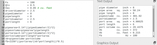
If you use this formula :
Fb = ( 13500 / 6.28 ) * ( portarea / ( ( Vb * portlength ) ^ 0.5 ) )
to find Fb ....
And the volume of the port becomes substantial ....
Should it become part of Vb ?
If you use this formula :
Fb = ( 13500 / 6.28 ) * ( portarea / ( ( Vb * portlength ) ^ 0.5 ) )
to find Fb ....
And the volume of the port becomes substantial ....
Should it become part of Vb ?
Thanks for that article.
You're welcome! Here's its primary AES paper: http://diyaudioprojects.com/Technical/Papers/Loudspeakers-on-Damped-Pipes.pdf
GM
GM .... : )
If you use this formula :
Fb = ( 13500 / 6.28 ) * ( portarea / ( ( Vb * portlength ) ^ 0.5 ) )
to find Fb ....
And the volume of the port becomes substantial ....
Should it become part of Vb ?
DMB/whoever can solve/manipulate the wave equation would have to answer this the most correctly since every junction has some sort of impedance mismatch, though IME, HR/similar program sims it's frequency dependent, so when it's very close to the same acoustic impedance they act as one, i.e. the box/vent converts from a BR with a 1/2 WL resonator [pipe vent] to a single 1/4 WL TL [what I consider the most technically correct].
FWIW, back before T/S, I used the pioneer's Av = Sd, Fp = Fs, with Vb [box + vent] chosen from published nomographs based on Fs. With tone controls, damping, they all sounded better overall in room than any typical mainstream consumer speakers I was exposed to including many inexpensive multi-ways.
GM
Av = Sd .... Area of vent = area of cone
Fp = Fs .... Fp ???? ........ Fb ?
Vb = Sum of vent volume and box volume
Fp = Fs .... Fp ???? ........ Fb ?
Vb = Sum of vent volume and box volume
Arne,
I just did a quick simulation with the Leonard Audio Transmission Line (LATL) package and I fond the following configuration looked pretty good:
4" Diameter, 24 inches long
4"-2" Reducer
2" Diameter x 4" long port.
Using the 4" to 2" reducer eliminates the need to do any cutting to attach the port.
And the great thing about the PVC route is that you can try different tube and port lengths very, cheaply and easily.
Here's my own PVC MLTL creation. With Pluvia 7.
Av = Sd .... Area of vent = area of cone
Fp = Fs .... Fp ???? ........ Fb ?
Vb = Sum of vent volume and box volume
Correct.
Pipe/horn tuning me and some others use[d] to differentiate it from the T/S Fb, Fc.
Correct.
GM
Using the 4" to 2" reducer eliminates the need to do any cutting to attach the port.
And the great thing about the PVC route is that you can try different tube and port lengths very, cheaply and easily.
 😀
😀Indeed! By the mid '60s it was relatively cheap with a large enough selection of sizes, connectivity to allow me and an old one armed DIYer to teach ourselves how to design/tweak intake, exhaust systems, TL speakers, etc., with a lot of help from this doc: https://ntrs.nasa.gov/archive/nasa/casi.ntrs.nasa.gov/19930092208.pdf
GM
So much for Vb = Vas ..... : )FWIW, back before T/S, I used the pioneer's Av = Sd, Fp = Fs, with Vb [box + vent] chosen from published nomographs based on Fs.
GM
Attachments
Ok, so I caught a bit of a flu, so no building yet...
(Did pick up a vintage Cyrus One amp to play with over the weekend with a set of B&W 610i's)

That was my attempt.It wasn't quite finished here and I was finding my way around the dampening as well...
 Enough for a mockup with a gasket and some home made clamps to test it on my Quad 34/405-2 combination with an Arcam Alpha CD player. Quite impressed, but in the end their sheer size and the need for a supertweeter and a sub made me decide to sell them. They made their way to Belgium where an enthusiastic builder finished them and told me that playing on them was as if a veil was taken away from all his music. 😀
(Did pick up a vintage Cyrus One amp to play with over the weekend with a set of B&W 610i's)
Thanks for the calculations. That looks very doable.Arne,
I just did a quick simulation with the Leonard Audio Transmission Line (LATL) package and I fond the following configuration looked pretty good:
4" Diameter, 24 inches long
4"-2" Reducer
2" Diameter x 4" long port.
My thoughts exactly. I mean, I once built MDF folded TQWT pipes based on a set of vintage Isophone broadband speakers from a historic cinema.Using the 4" to 2" reducer eliminates the need to do any cutting to attach the port.
And the great thing about the PVC route is that you can try different tube and port lengths very, cheaply and easily.
That was my attempt.It wasn't quite finished here and I was finding my way around the dampening as well...
That looks great. Would love to hear them play. 😉Here's my own PVC MLTL creation. With Pluvia 7.
- Home
- Loudspeakers
- Full Range
- Calculate a PVC Pipe speaker with 3.3" driver