Good Afternoon,
While my title may be confusing here's what I want to do. I have a 12B4 preamp that I built years ago and absolutely love. It's since been moved to my living room. I always turn the preamp on and let it warm up for a bit before amps come on. I'd like to automate that feature of the safety of my gear.
Is there a simple circuit that can be built to disconnect preamp outputs during warm-up, and would open fast enough to limit/eliminate turn-off pop during shut down?
The more I think about this the more I wonder if I should be adding a delay to the amp turn-on circuit and leave the preamp as-is if there's no logical solution.
If this has been covered before please link me as I am not totally sure of the terminology.
Thanks everyone.
Yes. The standard approach consists of three pieces: (1) a DPDT relay which connects the preamp's output jacks to either Ground, or to the preamp circuits' output terminals; (2) a circuit that detects whether the preamp's on/off switch is in the OFF position; (3) a circuit which delays about 20 seconds during power-on but about zero seconds during power-off.
These loose and general ideas need to be customized for your particular preamp.
To name one example, the relay's coil voltage needs to be chosen. Which is more conveniently available inside your preamp: +5VDC? +12VDC? +24VDC? Typical relay coils draw about 0.5 to 0.8 watts; divide that by the DC voltage to get the amperes.
Then a delay circuit needs to be designed which operates at that specific DC voltage.
Then someone will need to analyze the existing power supply of your preamp, to determine the easiest / smallest / cheapest / most elegant way to immediately detect that the power switch has been flipped to OFF.
I've used these for it before. If you need more than 10 seconds, there are other boards, but easiest to make either the resistor or the cap larger for a longer TC.
NE555 DC 5V 12V Delay Relay shield Timer Switch Adjustable Module Board 0 To 10 | eBay
Use this to drive a DPDT relay or use two of them, one for each channel.
NE555 DC 5V 12V Delay Relay shield Timer Switch Adjustable Module Board 0 To 10 | eBay
Use this to drive a DPDT relay or use two of them, one for each channel.
No. It won't protect from power glitches, it only delays B+ at power on. The protection from power glitchesSomething like this could do the trick if you are a tube fundamentalist.
was however not mentioned, it's a second feature. It could be served by an external ground-protection relay
that needs reset at power glitches.
The unit in #4 seems to be a good candidate to solve the problem. And instead of running mains
across it it could be used to control a SSR mounted inside the power amp.
Last edited:
Requests for simple delay circuits seem to crop up quite often.
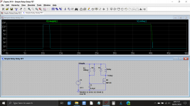
This is a very simple circuit using just one power FET (a small 2N7000 type is ideal as well... its not critical) and the circuit could be powered from the AC heater supply via a bridge or a single half wave rectifier and a small reservoir cap to ensure the relay drops out smartly on power off.
The delay can be set to pretty much any desired value by playing with the time constant of the R/C network. Electrolytics are fine if you ensure R is low enough to swamp any leakage.
The circuit is not ground referenced to anything in the amp and can float. The relay contacts are normally closed and short the audio to ground in the mute condition.
This shows the supply rise and fall and the relay operation.
Attachments
Of course I have a biamped system that also incorporates a subwoofer amplifier that's capable of drawing more current than my wall socket is ready to provide... Total of four power amps and 900wpc. I never see much past idle current though.
I am using a power center unit with a trigger on feature that works with anything below 30vdc. My heaters are DC in this preamp so I could use heater voltage to start the sequence. I think maximum delay on the power center is only 10 seconds which may not be long enough.
I need to read about the options already posted, but thanks for all the help so far.
No. It won't protect from power glitches, it only delays B+ at power on. The protection from power glitches was however not mentioned, it's a second feature.
At power on, it turns on the relay after some delay. The relay is used to short the outputs rather than to switch the supply.
At power off, the relay switches off quickly because the capacitor C10 in parallel with its coil is quite small.
During power glitches, C11 may not discharge fully, so the delay after the power comes back on will be shorter than it usually is. Then again, if it is a short glitch, the tubes will still be warm anyway, so who cares? Note that grid conduction of the ECC81 helps to discharge C11 quicker than it normally discharges, so if you want to reduce the discharge time constant during power dips, reducing R11 and R12 could help.
The unit in #4 seems to be a good candidate to solve the problem. And instead of running mains across it it could be used to control a SSR mounted inside the power amp.
How do you know? I don't see any information anywhere on how that circuit behaves during power glitches.
MY concern for protection against power glitches is that they may kill tubes, especially rectifier tubes. That's why i find it of value not to turn on an ampAt power on, it turns on the relay after some delay. The relay is used to short the outputs rather than to switch the supply.
At power off, the relay switches off quickly because the capacitor C10 in parallel with its coil is quite small.
During power glitches, C11 may not discharge fully, so the delay after the power comes back on will be shorter than it usually is. Then again, if it is a short glitch, the tubes will still be warm anyway, so who cares? Note that grid conduction of the ECC81 helps to discharge C11 quicker than it normally discharges, so if you want to reduce the discharge time constant during power dips, reducing R11 and R12 could help.
How do you know? I don't see any information anywhere on how that circuit behaves during power glitches.
shortly after it has been turned off , wait at least 30s.
Second quote , i find post #4 to be a good solution to the turn on problem,
while ignoring the power glitch, which it does not protect from.
A general protection from powerglitches is those ground-fault protectors
that needs manual reset after power fail, powering via one of these will
protect from glitches ( but not from a user that deliberatly cycles the power button).
User 240z4u needed solution of one problem, which has been suggested. I
am guilty of adding the second problem ( power glitches) , which i might
should have avoided as it has nothing to do with the original issue.
Fair enough, but no circuit that only controls an output mute relay can reduce rectifier tube stress during brown-outs.
Are there ground fault protectors that switch off when there is a dip in the mains voltage? The ones I have only switch off when the hot and neutral currents don't match.
Are there ground fault protectors that switch off when there is a dip in the mains voltage? The ones I have only switch off when the hot and neutral currents don't match.
Yes, i have such a device, when power is losyt one have to "reset" .Fair enough, but no circuit that only controls an output mute relay can reduce rectifier tube stress during brown-outs.
Are there ground fault protectors that switch off when there is a dip in the mains voltage? The ones I have only switch off when the hot and neutral currents don't match.
I bought at "clas ohlson"
Jordfelsbrytare med stickproppsanslutning | Clas Ohlson
- Status
- This old topic is closed. If you want to reopen this topic, contact a moderator using the "Report Post" button.
- Home
- Amplifiers
- Tubes / Valves
- Circuit to disconnect preamp output during warmup?