Yes, it looks similar but with a lot of ultra capacitors and the principle will be different.ConditionerPi will be like this?:
Raspberry Pi Power
Ian
@IanCanada,
First, I applaud your UcConditioner. Having used your developmental UCPi Ultracap output buffers as my standard BEST source->DAC supplies for over 6 months, I continue to be very happy with the improvements UCs as the final power supply buffer caps provide.
I currently have 6 DIY'd point-to-point UCPis on my Allo Katana and my Ian GB setup. BUT using the UCPis for these is a labor-intensive process AND only for an advanced DIY'er. Before use I have to pre-charge all of the UCs to the target voltages (5V for the USBridge Signatures and the 2 Katana 5V rails, 3.3V for Ian's FiFoPi and DM ES9038Q2M DAC) before connecting them. For 5V supplies, your UcConditioner will make UC buffers an easy-to-implement option for any general DIY'er AND make a significant improvement in the 5V non-isolated rail of your LiFePO4 supply.
AND while I'd love to see a 3.3V version of the UcConditioner, I know that using pre-charged UC pairs in parallel with 3.3V rails on your LiFePO4 supply is a good way to provide UC goodness to 3.3V rails. OTOH, my standard DAC and FiFoPi supplies use Uptone Audio LPS-1.2 Ultracap supplies as the base 'float-charging' supplies for my UCPi buffer setups. AND in my tests so far, I prefer that to the hybrid LiFePO4/UCPi combos. BUT at almost $400 each, multiple LPS-1.2s are out of budget for many DIY'ers AND your LiFePO4 supply becomes a much more cost-effective option. AND as we've discussed privately I still need to try the hybrid LiFePO4 supply / UCPi with the newer 325F Maxwells with significantly lower ESR than the 350F units I used before. These newer 325F UCs were a good upgrade over the older 350F ones used in my standard supply setup and I expect similar results when to make a hybrid UC/LiFePO4 setup.
I'm also excited about your ConditionerPi. This could be quite a boon for many RPi users. I've used an additional cap or two on the RPi 5V rail almost from the beginning (as suggested by Soundcheck). While it made a noticable improvement, it was not large. Using a UC output buffer on the 5V rail is a MUCH larger improvement in my setups and to my ears. Powering an RPi or equivalent's 5V with a UC buffer, ALSO I've found that it works well with an AC-powered supply instead of a more expensive pair of LPS-1.2's. In the past my best 5V supply for RPis was a pair of LPS-1.2's paralleled through an MPAudio dual-section 3||LT3042. Now I use either a modified K&K Audio Low Voltage supply (larger caps & beefier diodes) or a modified Allo Shanti (switch bypassed, case and caps damped) as the 5V supply to the UC buffer.
Given the addition of your UcCondition, ConditionerPi, and the ability to add UC pairs to the 3.3V rails on your LiFePO4 supply, you're providing a pretty advanced set of high-quality power supply tools to even average DIY'ers. I'm VERY curious where you will go from here, especially on a pure UC supply, IF you are still pursuing that. AND if you are planning to introduce products to provide UC output buffers on 3.3V rails and those higher than 5V.
Greg in Mississippi
@prohvesor, I agree that the other rails on the RPi are also important. I've used the LDOVR.com Mezzanine board that you linked to modify a couple of RPi 2Bs to fully linear-regulated power on the 3.3V and 1.8V rails. Initially I powered them with my then-best dual LPS-1.2 paralleled through a dual-section MPAudio board as above, set to 6V to allow dropout headroom for the on-board 5V LT3045 regulators. After hearing the benefit the UC buffers made feeding the 5V to un-modified RPis, I bypassed the on-board 5V regulators and fed the Mezzanine board 5V with UC buffers. In both configurations, these were significant sonic upgrades over stock RPis, no matter what they were fed.
BUT that setup has several drawbacks to my mind...
1. It is limited to the earlier RPis such as the 2B. I understand that the earlier 3B model can also be modified this way, but requires an additional 1.2V rail as I remember. Later RPi3 models and 4s use a different DC-DC converter chip and have checks in the Bios to ensure it powers up ok, so you can't easily eliminate it.
2. Modifying an RPi (2B in my case) to work with one of the LDOVR.com Mezzanine boards is both challenging and expensive. Unless you are good with SMD component soldering, your best bet is to get the board pre-populated by Alexey for $100. AND you still have to identify good insertion points for at least the 1.8V AND remove the on-board DC-DC converter chip. On my implementations, to keep the I2S path to the driven DACs as short as possible, instead of mounting the Mezzanine on top of the RPi, I mounted it under the RPi 2B's and used leads to connect to selected insertion points for the 5V, 3.3V, and 1.8V. Then to remove the on-board DC-DC chip, I first tried my SMD hot air rework station, but found I had a hard time with just the hot air. I ended up using a large (40watt) soldering iron directly on top of that chip after breaking off as much of the plastic chip top as I could. In the process of learning this I ruined one RPi 2B trying to remove that chip. So I used 3 RPis to get 2 modified ones!
You can see pictures of one of my RPi2Bs modified with the Mezzanine board and some additional comments in post #25 of this thread:
Mezzanine Power board for Raspberry Pi
Honestly, the sonic results EVEN with the limitations and expense were well worth it. Quieter backgrounds, overall more natural sound. At least they were until Allo introduced the USBBridge Signature. Consider that unit an oversized RPi with ALL rails on ALL chips supplied by their own individual local linear regulator. It also has the benefit of an additional wired Ethernet chip to remove the resource bottleneck of the shared Ethernet/USB chip in the earlier RPis AND a dedicated USB-hub-based USB output designed to provide good signal integrity on the USB feed to USB-input DACs in a manner similar to the Uptone Audio Regen and similar devices. For $100 more than a populated Mezzanine board and an RPi, you get a ready-to-use RPi replacement with a more extensively buffered power network. Sonically replacing my linear-regulation modified RPis with USBBridge Sigs was another significant positive step up in SQ.
I take Ian's response to say that the challenges of providing local UC filters to the other rails is not worthwhile EXCEPT possibly for the 3.3V rail as it is the only other one that is exposed on the RPi expansion header. Seriously, if you want to save some $ and get a great result, go with the LDOVR.com Mezzanine board. AND if you are ok spending a bit more coin for an even better result, get an Allo USBBridge Signature.
AND both benefit from UC-sourced 5V power and I suspect will also benefit from the addition of Ian's upcoming ConditionerPi.
Greg in Mississippi
P.S. @prohvesor, I just looked at the picture in your post above. Those 3.3V and 1.8V test points were the insertion points I used on my 2nd linear-modified RPi and what I would use for a future mod IF I ever do one again (which I now doubt, having 2 already here and 3 USBBridge Sigs too!).
Last edited:
@IanCanada,
AND if you are planning to introduce products to provide UC output buffers on 3.3V rails and those higher than 5V.
Greg in Mississippi
It would be nice.
Actually I need 3.3V rails only, as I have BeagleBoneBlack and it supports both 3.3V & 5V input.
Hi Ian
In your Fifo manual you say you can use a 3.3v battery with a super cap.
I will purchase your battery psu but I am not clear what project is the super cap and if available today?
Also what is the best psu to power the battery psu?
Thank
Simon
In your Fifo manual you say you can use a 3.3v battery with a super cap.
I will purchase your battery psu but I am not clear what project is the super cap and if available today?
Also what is the best psu to power the battery psu?
Thank
Simon
I will buy Ian’s lifepo4 when it’s completed with ultracaps, to power Fifo’s isolated side.
Any news on when this will be possible ? Ian ?
Any news on when this will be possible ? Ian ?
Hello,
As you can see there is no space available on the original circuit to add ultracaps. I would just make a nice sturdy board to mount them closely to the load.
If i remember well you dont have to charge the ultracaps by means of a resistor if you use Ian's original board because it will limit the charging current with some electronic " trick "
Greetings, Eduard
Attachments
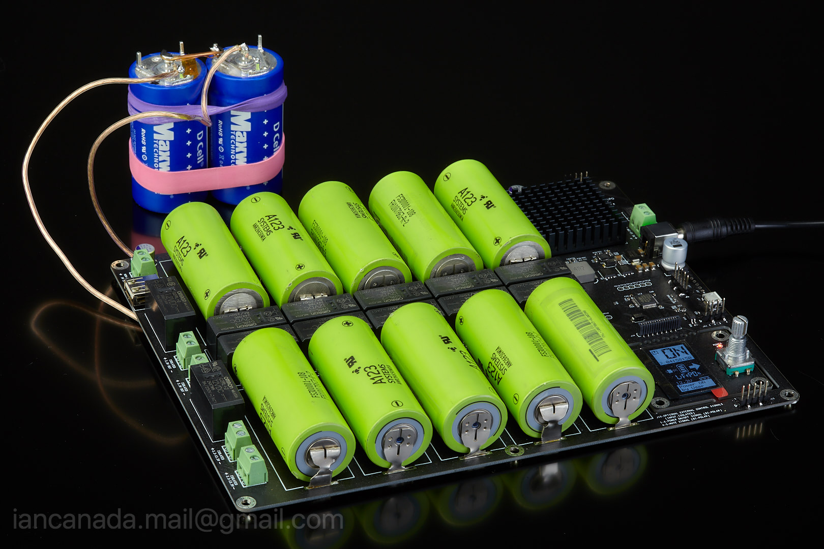
Ultra capacitor/LifePO4 hybrid power supply could be so far the best 3.3V rail in the world. I found a very easy solution to upgrade my LifePO4 power supply board in this way.
3.3V LifePO4 battery power is already very good for low noise clock and DAC applications. However, ultra capacitor /LifePO4 hybrid power supply has even lower internal ESR. So with the upgrade, both response performance and low noise performance can be improved even more. There could be no any other power supply solution can be better than this.
I’ve tried using this upgraded hybrid 3.3V rails for the FifoPi clean side and VCCA of ESS DACs with good result. The improvement of sound quality can be heard clearly during the listening test. I’m very happy with it.
If you had my LifePO4 power supply, I would ask you doing this upgrade today not tomorrow. It will give you a big surprise.
To do so, you will need only 3 or 2 steps,
STEP1:
Prepare a pair of ultra capacitors. You can use either BCAP0350 E270 T13 or BCAP0325 P270 S17.
The second one has lower ESR almost as half as the first one. Connect a 470ohm passive balance resistor in parallel with each cell and then connect the two capacitors together in series.
Also prepare two pieces of wires, AWG18 or bigger.
If you don’t have other way to pre-charge your ultra capacitor package, you will also need a power resistor around 3 ohms.
UltraCapacitorLifePO4HybridPowersupply1 by Ian, on Flickr
STEP2:
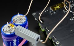
Solder a wire between the negative of the battery cell of the LifePO4 power supply to the negative of the ultra capacitor package, and a wire from the positive of LifePO4 battery cell to the positive of the ultra capacitor through the power resistor (Or, you can solder them directly to the taps if you use battery holders). Leave them for a couple of hours until the capacitor package is pre-charged to higher than 3.0 volt.
BT6 is corresponding to 3.3V rail on J1
BT7 is corresponding to 3.3V rail on J2
If you can pre-charge the ultra capacitor package to around 3.3V in other way, you can escape this step.
CAUTION: Make sure no any short circuit happens during assembling and soldering. It will be very dangerous because huge energy stored in battery cells even without a DC power connected.
UltraCapacitorLifePO4HybridPowersupply2 by Ian, on Flickr
STEP3:
Remove the power resistor. Make sure both positive and negative terminals of the ultra capacitor package are connected very well to the battery cell.
Now you are having the upgraded hybrid power supply. It’s really not difficult. You no longer need to disconnect or to pre-charge the ultra capacitor package any more as long as you have battery cells installed. You are done!
Re-connect the upgraded hybrid power supply back to your system as before, enjoy the music!
UltraCapacitorLifePO4HybridPowersupply3 by Ian, on Flickr
I would suggest to upgrade the 3.3V rail for the FifpPi clean side first, and then the3.3V rail for the ESS DAC.
Have a good weekend.
Ian


Hi Ian, are you working to prepare a new board to manage the hybrid part of your lifepo4 ? Could be very useful to have a board to put on the lifepo4 that is able to manage the first smart charge of the ultracaps. Something like your Uccondicioner but not limited to the 5V line but also to the others 3.3v
Hi All, great work here
IMO, ESR is not the secret sauce to the sound quality differences between battery & ultracapacitors. If it were ESR would not the wire length & gauge not have a significant effect on this?
Is it not more likely that the difference between the mode of production of DC between battery (chemical) & ultracapacitor (electrostatic) not be of more significance. As is often the case in audio we take a single figure & use it as a measure of quality, rather than the speed of delivery of current over wide frequency range. It would be very interesting to see such a plot for both LiFePO4 & Ultracapacitors well into MHz frequencies. It would also be interesting to see how complex dynamic current supply plots .e. current at 100Hz timing while also supplying current at 10KHz timing and/or 10MHz timing i.e. testing the stability of the current being supplied.
The icing on the cake would be to then see how such plots Vs the same plots for voltage regulators translate into measurements which hint at audible differences.
Sorry if this has been covered before - if so please ignore.
Last edited:
Hi All, great work here
IMO, ESR is not the secret sauce to the sound quality differences between battery & ultracapacitors. If it were ESR would not the wire length & gauge not have a significant effect on this?
Is it not more likely that the difference between the mode of production of DC between battery (chemical) & ultracapacitor (electrostatic) not be of more significance. As is often the case in audio we take a single figure & use it as a measure of quality, rather than the speed of delivery of current over wide frequency range. It would be very interesting to see such a plot for both LiFePO4 & Ultracapacitors well into MHz frequencies. It would also be interesting to see how complex dynamic current supply plots .e. current at 100Hz timing while also supplying current at 10KHz timing and/or 10MHz timing i.e. testing the stability of the current being supplied.
The icing on the cake would be to then see how such plots Vs the same plots for voltage regulators translate into measurements which hint at audible differences.
Sorry if this has been covered before - if so please ignore.
I think members Jackinnj and Gerhard have measured Lipofe cells and found that their output impedance and noise could not be bettered by regulators. IIRC the noise levels even when loaded were below -150dB across the audio band. Aside from super capacitors, nothing else comes close.
I think members Jackinnj and Gerhard have measured Lipofe cells and found that their output impedance and noise could not be bettered by regulators. IIRC the noise levels even when loaded were below -150dB across the audio band. Aside from super capacitors, nothing else comes close.
Thanks
I'll have a look for Jackinni & Gerhard measurements.
It sounds from your description that these were measurements may have been with static conditions? I believe the real advantages of this approach over regulators may be their behaviour when supplying current under dynamic conditions. For instance digital devices can have varying current demands at high frequencies & this is often where the major sonic benefits are being realised
Most of us laptop supplies, and yes it only charges when switched off.
Thanks
Thanks
I'll have a look for Jackinni & Gerhard measurements.
It sounds from your description that these were measurements may have been with static conditions? I believe the real advantages of this approach over regulators may be their behaviour when supplying current under dynamic conditions. For instance digital devices can have varying current demands at high frequencies & this is often where the major sonic benefits are being realised
You'll have to look for the results. They are buried on the forums, somewhere. The biggest subjective gains Ive heard from using LiPoFe cells is to power oscillators. Their low noise really helps there.
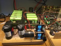
I followed the idea of Greg for the ultracaps in this post: https://www.diyaudio.com/forums/pow...-explore-plus-build-thread-4.html#post5936139
As a diy drone builder I had some connectors lying around.
The ultracaps are used on the ps for the fifopi and andrea mori clock (3.3v supply).
It’s now running in. I am very curious of the results.
The caps are connected in parallel to the batteries. I would like to use them as a r-c filter on the battery supply but this is not easy to do. I expect using a filter point with the resistor will result in even less noise from the battery.
It could be done by just connecting them on the output of the battery supply but in that way the capacitors will drain when power is off (it is behind the relais) and will need filling at power up, and as filling them with a 3,9ohm resistor takes about one hour this is not usable.
Has anyone found a solution for this by modifying the battery output line to the relais and inserting the r-c filter in this way?
Regards,
Attachments
Last edited:
How about putting an on/off switch after the ultracap before the load. I think the entire PS can sit indefinitely charged if there is no load.Has anyone found a solution for this by modifying the battery output line to the relais and inserting the r-c filter in this way?
Regards,
@supersufer what’s the name of the connectors you are using on the ultra caps please?
They are T-connectors and are used for lipo batteries: https://hobbyking.com/nl_nl/catalogsearch/result/?q=T-connector
The XT-60 or XT-90 are also a good choice for high power applications.
Last edited:
How about putting an on/off switch after the ultracap before the load. I think the entire PS can sit indefinitely charged if there is no load.
The battery charger will switch itself off after a preset time, maximum 12hours. So the capacitors will not be in contact with the batteries and will discharge itself.
- Home
- Amplifiers
- Power Supplies
- Develop ultra capacitor power supply and LiFePO4 battery power supply