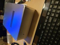
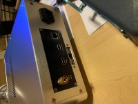
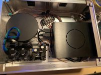
One more Allo device with L-Adapter PSU. Just finished its assembly and initial test. Did not connect my USB DAC to it yet for SQ comparison, but planning to do that next week. All Raspberry Pi related functions are working and Volumio player application is functioning well (again, DAC is not connected yet).
Running 5.15V and that is enough voltage/current to run my USBridge Signature it with 2.5" HD connected.
Running 5.15V and that is enough voltage/current to run my USBridge Signature it with 2.5" HD connected.
Attachments
Last edited:

Nice box up. Congrats.
Yes indeed....beautiful implementation.
Stupid Question: could it be that there is almost no ripple measurable when 1,2 Ampere is drawn constantly?
When measuring at the DC output connector with so fast horizontal sweep, yes possible. If you go down to 1ms maybe able to see more. Engage the 20MHz scope limit as well.
Hello Salas
greetings i would like to try your Ladaptor for my rasberry pi dac
transformer secondary i want to keep it 0-8 volt AC 4 AMPERES
is it ok just drew a rough pcb
warm regards
Andrew
Hello!
I wanted to assemble ATX power for Asus Z97M: +12v, +5v, +3v. So need some compact L-A boards. We together could order several boards of your version in China.
Are you interested?
No. You don't have my permission to alter my named design. That board would not work anyway because of mistakes. L-ADAPTER is meant to replace external single voltage SMPS bricks so its fine as it is. That's the majority of audio gear applications. Specialized multiple output version for ATX motherboards and such is not something I am interested in. And it's not going to be small and efficient enough either.
No. You don't have my permission to alter my named design. That board would not work anyway because of mistakes.
No problem Salas, I just looked for different variants.
L-ADAPTER is meant to replace external single voltage SMPS bricks so its fine as it is. That's the majority of audio gear applications. Specialized multiple output version for ATX motherboards and such is not something I am interested in. And it's not going to be small and efficient enough either.
Yes, linear PSU for top PC transports are quite large. May be it is no option to make it quite small.
PS: By the way, Raspberry Pi and PRO audio is incompatible things. The only choice is full PC mother boards + Linux.
Last edited:
Ok found my fault at measuring, everything fine now...
Other Question : Im using a toroid with 15V Ac, and configured it to 12 volts..
Between fuse and Vout I measure 12V, with a 10ohm resistor connected... Is this ok or too much? Configuring the Adapter to 16V, there is still 4v between fuse and Vout...
Other Question : Im using a toroid with 15V Ac, and configured it to 12 volts..
Between fuse and Vout I measure 12V, with a 10ohm resistor connected... Is this ok or too much? Configuring the Adapter to 16V, there is still 4v between fuse and Vout...
Ok found my fault at measuring, everything fine now...
Other Question : Im using a toroid with 15V Ac, and configured it to 12 volts..
Between fuse and Vout I measure 12V, with a 10ohm resistor connected... Is this ok or too much? Configuring the Adapter to 16V, there is still 4v between fuse and Vout...
3V difference is OK because >2.5V precaution
Working on one of these and have to say what a clever trick it is to use the fuse resistance as part of the power supply filtering. Never occurred to me and yet it is so obvious. Now.
This is something I will incorporate into other supplies. We are always trying to minimize the effect of the fuse and I suspect this is the best one can do short of living dangerously with no fuse at all.
As usual, SALAS is always thinking. Thanks for the gift.
This is something I will incorporate into other supplies. We are always trying to minimize the effect of the fuse and I suspect this is the best one can do short of living dangerously with no fuse at all.
As usual, SALAS is always thinking. Thanks for the gift.
Working on one of these and have to say what a clever trick it is to use the fuse resistance as part of the power supply filtering. Never occurred to me and yet it is so obvious. Now.
This is something I will incorporate into other supplies. We are always trying to minimize the effect of the fuse and I suspect this is the best one can do short of living dangerously with no fuse at all.
As usual, SALAS is always thinking. Thanks for the gift.
Hello!
May I ask some questions:
1) So you think that fuse works as filter but why. Fuses are not best for audio purpose.
2) If needed 5v x 5A PSU, so how much must be a diameter of transformer wire? May be 1.6mm, how you think?
Any amount of resistance will result in a filter.
The fuse is being fed DC voltage not AC voltage which will make the fuse operate at a higher temperature which might be a disadvantage but will not be "vibrated" by the AC voltage so it might be a more stable resistance than it would be otherwise.
One way or another you are going to deal with the sonic penalties of a fuse. If it better to have it at the beginning of the power supply or near the end? This is something that might depend on each application.
I wanted to hear it for myself so I exchanged a filter resistor with the fuse in my First Watt SIT 1s which have non-standard supplies. Instead of the stock power transformer/rectifier/cap bank I used a higher secondary voltage transformer/superior rectifier diodes/Lundahl filament choke/cap bank/series resistance/cap bank.
With the fuse in the place of the resistor i am getting higher voltage since the fuse is of lower resistance. My voltage had been lower than it should have been so this was an advantage. I know this is far from an apples to apples comparison but i can say that I hear no ill effects and know that I am hearing some good effects. Of course, I cannot say this is due to the fuse since the voltage has changed and could well be the reason for the small improvement.
One has to deal with the fuse one way or another. It makes sense to me conceptually that the fuse would be less "bad" being fed DC and between two capacitor banks one might think some of the anomalies of a fuse would be lost in the electrolytic goo. Having some fun there.
These amps are only used above 500 Hz. and live the life of a show dog. Never stressed - driving JBL 2441s.
One thing to remember - if if you do blow a fuse with this arrangement you will need to bleed the preceding capacitor since it will retain its voltage for quite awhile.
Do not use 3AG fuses - these are never rated for DC use. There are 2AG fuses that are rated for DC.
I have been surprised at the variation in fuse ESR. The lowest I have found are the fuses that look like resistors. These must have some soft start provision - I use thermistors in series that I bypass after turn on.
12vac safe for 5vdc ?
I plan on using the L-dap for a Beagle Bone Black board that might require up to 2 amps short term and 1 amp continuous at 5vdc.
I have a xfmr with 12vac output at 2amps.
Wondering if the L-dap can tolerate the required voltage drop.
12v * 1.414 = 16.968v needs to drop about 12 volts.
I know a 9vac xfmr would be best.")
I plan on using the L-dap for a Beagle Bone Black board that might require up to 2 amps short term and 1 amp continuous at 5vdc.
I have a xfmr with 12vac output at 2amps.
Wondering if the L-dap can tolerate the required voltage drop.
12v * 1.414 = 16.968v needs to drop about 12 volts.
I know a 9vac xfmr would be best.
Last edited:
The L-Adapter's pass transistor will long term tolerate it if suitably sinked. Test how things initially go for sink temperature given the particular transformer and load.
Run your likely tasks on that computer and watch thermals. If not tolerable, say sink runs always above 65C, upgrade the sinking accordingly. Make it external.
Its not easy to break it during evaluations. Even if it will burst to 100C sink temperature. But don't sustain it too high, keep an eye on temperature all the time.
The L-Adapter's pass transistor will long term tolerate it if suitably sinked.
, keep an eye on temperature all the time.
Thanks, will try.
Finally got my L ADAPTER in place.
Since I was making it to replace a 19 volts switcher part of the HDPLEX 200 watts supply I wanted to maximize current delivery so used a large heatsink and wired point to point so I could use heavier gauge wire than would be possible with the PCB. Along with a different rectifier - my favorite stth6110 in full wave, but not bridge.
I am using the ASROCH J3455B motherboard which seems to have unusually good USB performance. Only USB is used. SATA is turned off in BIOS along with about everything else that can be turned off other than HPET. Set for ECO performance which slows down the CPU.
The USB is taken from the motherboard headers and are powered externally.
USB for the DAC gets is power from an ULTRA BIB and the USB thumb drives (MLC) are supplied by an AUDIOWIND reg which is pretty good for second tier components.
I had no idea how much power the board was going to require.
There was no problem in booting. What took me by surprise is how little power the board requires. The heatsink stayed cool through three hours of listening.
I guess it did not require all of the trouble I went to!
There was no immediate WOW - the HDPLEX SMPS supply must be pretty good. What was interesting is after listening for awhile I realized there was a great reduction in noise/distortion about approx 3kHz. The kind of thing you only notice with time.
I had been setting the level of the tweeters lower than what REW suggested would be a good level - not flat but an easy downwards slope. But that setting did not sound right - I would have to lower the tweeter level one or two additional dB to be able to relax.
With the L ADAPTER I was able to go up one dB without any harshness and allowing a better balance. I can only assume this signals a significant drop in dynamic distortion.
I guess once you remove the peripherals the motherboard does not use THAT much power.
There is no question powering the USB outlet that supplies the DAC makes a big sonic difference. Not so much for the drives but I thought I was going to need the margin for the L ADAPTER. I will keep it as is, nonetheless,
Since this was not going to be used for anything other than this I used 10 LEDs - so I find i am just above 19 volts (which is what I wanted) with the trim pot turned to maximum resistance.
SALAS, would there be any advantage to shorting one of the LEDS and setting the trimmer at a lower amount of resistance or is this another example of the proverbial 144 of one; 12 dozen of another?
Thanks for another great circuit.
I go into all of this detail because this little motherboard sounds really good with the HDPLEX power and better still with L ADAPTER.
Using WTF for operating system/music player. USB in and USB out. To think I used to think USB was the worst thing that ever happened to audio. I figure there must be something to sticking to one "format" input to output?
A very good inexpensive music player!
Since this was not going to be used for anything other than this I used 10 LEDs - so I find i am just above 19 volts (which is what I wanted) with the trim pot turned to maximum resistance.
SALAS, would there be any advantage to shorting one of the LEDS and setting the trimmer at a lower amount of resistance or is this another example of the proverbial 144 of one; 12 dozen of another?
Thanks for another great circuit.
Hi, you are welcome, interesting experiment with powering a motherboard.
Regarding your question, it seems rather contradictory to me. Because if you would want to stay in the same Vout territory but without trimmer resistance contribution, you would not want to short an LED but add one. In my view just back up the trimmer a little closer to 19V as it is. So you lose some contribution without any further modding. If its a small margin, mod it and judge for yourself. No trimmer makes for a bit stiffer but less well filtered Vref by the shunt capacitor there. PSRR governor at the node of interest is the high value chip CCS impedance vs the much lower Leds+trim vref impedance. Which is a high enough ratio already by design.
- Home
- Amplifiers
- Power Supplies
- L-Adapter