Could you try a discreet darlington in place of M1. Thanks.
If you connect it the same way as M1, namely, if you use two PNPs in a common emitter configuration for the +VREG,
then you're going to get A LOT MORE gain out of the output transistor (since its gm is so much higher than a MOSFET gm) and you're going to have A LOT MORE to be worried about, stability wise.
On the other hand, SPICE only answers the questions you ask it. The questions you don't ask, meet with stony silence.
Mark,
I don't disagree....but I only wanted Jeff to compare Darlingtons vs Mosfets as pass elements and I would attach it to the other leg of the differential observing polarity of course. See schematic I attached.
Jeff is on a voyage of discovery but you seem to have a bee under your bonnet for some reason.🙂
Jam

Enjoy the voyage of discovery. Perhaps it may include a brief side-trip to the land of charge pumps and ultra low loss MOSFET source followers, delivering the hard-to-get-it-wrong stability of (follower + single pole amp) circuits, without the corresponding headroom penalty.
Or, voyagers blessed with extreme bravery can pursue the Borbely shunt regulator circuit in #612, whose cascade of three inverting gain stages appears to be frequency compensated by at least four capacitors (!). Getting that thing to operate stably at both 5% load and 95% load, would be quite an accomplishment.
Another PSU Transient Load Tester (chop chop box)
Yes indeed, it does oscillate. This is it approaching 180º:
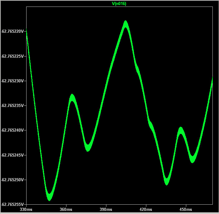
Interestingly, it doesn't materially harm the performance. This is showing a 30uV delta-V reaction to a 3mA delta-I, so it's still within the 10mOhm spec. And once it gets to 180º and runaway gain, all it does is hammer the signal dead flat.
But is this generating a ton of heat in the pass device?
Interestingly, it doesn't materially harm the performance. This is showing a 30uV delta-V reaction to a 3mA delta-I, so it's still within the 10mOhm spec. And once it gets to 180º and runaway gain, all it does is hammer the signal dead flat.
But is this generating a ton of heat in the pass device?
Attachments
While ugly pictorially, the oscillation frequency is around 20KHz. Since the device is expected to operate at that frequency anyway, it doesn't seem like that should generate excess heat.
Is there really such a thing as benign oscillation?
I tried moving the pole out to the MHz range and then squashing it with a zero. This looked good on the AC analysis but had no effect on the oscillation in the transient analysis? (And it was a bunch more parts.)
Is there really such a thing as benign oscillation?
I tried moving the pole out to the MHz range and then squashing it with a zero. This looked good on the AC analysis but had no effect on the oscillation in the transient analysis? (And it was a bunch more parts.)
Have you collected some simulation results (A, B, C), which suggest that other simulation results (D, E, F) are highly suspicions?
Perhaps something along the lines of:
Or, traversing the path in the opposite direction,
Perhaps something along the lines of:
Do the phase margin and gain margin simulations suggest that oscillation is simply impossible?
Or, traversing the path in the opposite direction,
Does the observed oscillation suggest that the phase margin and gain margin simulated results are simply mistaken?
Hi Mark,
I'm not sure.
I'm injecting my AC into the base of the feedback transistor in the LTP. Measuring the output gives me stellar margins.
However, if I probe the output of the LTP I get a hump which goes above unity gain (around 25KHz), and the phase is over 180º there.
First off, are those reasonable strategies for testing the stability?
Next, the ugly wave forms I observed in the transient analysis only appear around 11KHz (and it's a very narrow window, disappearing at 10.98KHz and 11.05KHz). That raises a suspicious eyebrow, but I'm also suspicious regarding whether or not I know when to be suspicious. 😉
Cheers,
Jeff.
Hi Jam,
I tried both a discrete Darlington (the best I found was a KSC1845/BDX77), and a hybrid-three-stage (KSC1845/TIP122).
The hybrid didn't work at all, and the best I could get the discrete was about 30X times worse output impedance than the MOSFET.
Cheers,
Jeff.
I tried both a discrete Darlington (the best I found was a KSC1845/BDX77), and a hybrid-three-stage (KSC1845/TIP122).
The hybrid didn't work at all, and the best I could get the discrete was about 30X times worse output impedance than the MOSFET.
Cheers,
Jeff.
Jeff looking good, this is what I kinda had in mind............mirror helps and circuit should be much more stable. It can be improved without much change.
Is this the topology you tried out the darlington and CFP? Could you sim them if possible. Thanks.
Possible topology for the pre-amp if pico agrees..........🙂
Mark,
I see you got over that massive lunch you had...................😀
Jam
Is this the topology you tried out the darlington and CFP? Could you sim them if possible. Thanks.
Possible topology for the pre-amp if pico agrees..........🙂
Mark,
I see you got over that massive lunch you had...................😀
Jam
Last edited:
First source follower pass device you've shown that omits a "gate stopper" and a "phase lead" capacitor in the feedback network --- deliberately?
Jeff,
Apart from what Mark brought you might consider zener protection for the mosfet if it does not have it.
I wonder if attaching the tail of the differential to negative supply might help performance, then again maybe not.
Jam
Apart from what Mark brought you might consider zener protection for the mosfet if it does not have it.
I wonder if attaching the tail of the differential to negative supply might help performance, then again maybe not.
Jam
First source follower pass device you've shown that omits a "gate stopper" and a "phase lead" capacitor in the feedback network --- deliberately?
No and yes. Missing gate stopper was accidental, but phase lead comp didn't seem to be doing anything.
Speaking of which, do I need the output capacitor? It doesn't seem to contribute anything....
- Home
- Amplifiers
- Pass Labs
- JamJar: an HPA-1-inspired power amp