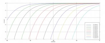
I recently listened to Nelson's Schade BAF discussion. Then I read ZM's M2/SEF thread. Below is the IXTN210P10T with 100K and 3K as the Schade resistors.
From left to right, Vgs = 2.7, -2.8, -2.9, -3.0, -3.1, -3.2, -3.3, -3.4, -3.5, -3.6, -3.7
I have an idea for this device in this configuration.
From left to right, Vgs = 2.7, -2.8, -2.9, -3.0, -3.1, -3.2, -3.3, -3.4, -3.5, -3.6, -3.7
I have an idea for this device in this configuration.
Attachments
I recently listened to Nelson's Schade BAF discussion. Then I read ZM's M2/SEF thread. Below is the IXTN210P10T with 100K and 3K as the Schade resistors.
From left to right, Vgs = 2.7, -2.8, -2.9, -3.0, -3.1, -3.2, -3.3, -3.4, -3.5, -3.6, -3.7
I have an idea for this device in this configuration.
The curves threw me off a bit till I saw that x and y axis is labeled with negative values, my brain works better seeing |absolute| current Id and Vds values.
Bloody dumb brain.
Last edited:

I could make a calculated result of the absolute value for both voltage and current and plot those. Same process as plotting transconductance. That would require at least a few seconds of work in the curve tracer software. Call me giga-lazy.
Actually, I like to see the sign of what I am measuring. For a depletion mode part, the sign of Vgs is opposite of the sign of the current. I like to see that opposite relationship both in the spreadsheet results and the axes of the plots. The hardware is a pile of sourcemeters that can work in all 4 quadrants of V-I. Positive and negative voltage and positive and negative current (source and sink).
Actually, I like to see the sign of what I am measuring. For a depletion mode part, the sign of Vgs is opposite of the sign of the current. I like to see that opposite relationship both in the spreadsheet results and the axes of the plots. The hardware is a pile of sourcemeters that can work in all 4 quadrants of V-I. Positive and negative voltage and positive and negative current (source and sink).
just ignore 2pd, keep up with good work
he's just trying to be dumber than M. ZM ........ no way , Jose!
🙂
he's just trying to be dumber than M. ZM ........ no way , Jose!
🙂
Brian, I think you should confirm HF performance in sim.
I can see why one would want to look at that. From a simplistic glance, you have a 3k resistor in series with nF of gate capacitance. The 3K resistor is going to choke the current required to charge the gate. At very high freq, the capacitor is zero ohms. At the freq where the input capacitance translates to 3k ohms, the voltage delivered to the FET will be 1/2 of the applied voltage (-6dB?). I just punched that into a spreadsheet and that is 53 kHz.
Funny enough, it would probably be simpler for me to actually measure this phenomenon than to try to use SPICE for it. I have more gear than SPICE skills.
I will put that on the list of things to do once the bias design actually works. I spent some hours today trying the Schaded PFET in a follower pair and the bias is tricky. There is a very narrow window where the bias is what you want. 10mV in the wrong direction gives you either 0 amps or infinity amps. I could see that from curve tracing the Schaded PET. There is a very narrow range of gate voltage where you can paint the curves on the screen.
depending how one is going to use Schade-d part , capacitances can be important or not
see comparison of measurements between so-so regular M2 vs. SEF amp in Babelfish M2/SEF amp
see comparison of measurements between so-so regular M2 vs. SEF amp in Babelfish M2/SEF amp
And don't forget to account for Miller effect on Cgd.
You also want to add an R from gate to source, makes biasing a lot easier as used in the original Zen amp article.
You also want to add an R from gate to source, makes biasing a lot easier as used in the original Zen amp article.
@woofertester
What curve tracer are you using? I search your previous posts but could not find a mention of it.
What curve tracer are you using? I search your previous posts but could not find a mention of it.
@woofertester
What curve tracer are you using? I search your previous posts but could not find a mention of it.
Keithley 2651A, 2636B, ACS Basic software. I have access to this equipment as part of my day job.
And don't forget to account for Miller effect on Cgd.
You also want to add an R from gate to source, makes biasing a lot easier as used in the original Zen amp article.
Thanks for the pointer. I will print it out and read it.
I have been using 220k ohms from gate to ground. with no DC path from gate to ground, zero current flows. The SIT requires close to 1uA to flow from the gate.
I will try a resistor from gate to source and see how that behaves.
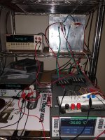
DEF + Schade P-FET + SIT
The Schade resistors are on the proto board in the foreground along with a 10k from SIT gate to ground. The 3K Schade resistor is between P-FET gate and SIT gate.
The picture is at 36.8 deg C. Ids 1.784 deg C.
At 45 deg C, Ids is 2.2A.
It is fairly simple to add resistance in parallel with the 220K Schade resistor.
Can this arrangement be called DEFiSChit ?
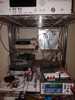
48.78 deg C. Removed the parallel resistor across the 220k resistor. Ids 1.79A. amps. I wanted to keep final current under 2A.
The DC offset is large; 2.25V. I am guessing that this can be corrected with a negative voltage applied to one or the other gate.
The DC offset is large; 2.25V. I am guessing that this can be corrected with a negative voltage applied to one or the other gate.
Attachments
or to voltage divider , so you can set DC offset
same as in DEFiSIT
I will do the voltage divider. I did that for the non-Schade Tokin DEF.
- Home
- Amplifiers
- Pass Labs
- Schade musings