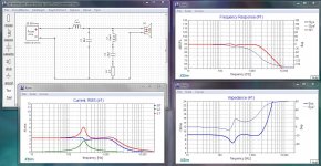
If the DC resistance of the 56mH inductor is 2.7 ohms or made up to that value then the series notch filter will work with 8 ohms being the minimum impedance for the woofer circuit.
Current in that circuit is limited to 7 amperes due to the inclusion of the notch filter.
There should not be any general db loss apart from that in the 1 ohm resistor.
C.M
Current in that circuit is limited to 7 amperes due to the inclusion of the notch filter.
There should not be any general db loss apart from that in the 1 ohm resistor.
C.M
I made a mistake using Xsim as I'm not used to it (I used it so I could expand on your work). Here's the impedance.
Please understand ... I was not proposing a solution. I was presenting the problem. As in why you should not do this.
I said it was a bad idea.
You asked what would happen.
I answered.
Last edited:
If you have unequal performance, bass traps may very well be your friend.
I really like the Soffit traps from GIK for wide and deep performance.
I really like the Soffit traps from GIK for wide and deep performance.
Yep... The OP has said that he would try fixing this by changing the room, which makes a lot more sense.
 Please do NOT quote the entire post just above yours. See the RULES section. Keep this forum clean.
I have removed the over quoting.
Here's my series notch at about 110Hz in my current three way. 4dB correction. No problem at all. 100W/8ohm

And it is more than perceivable.
And it is more than perceivable.
Last edited:
Here's my series notch at about 110Hz in my current three way. 4dB correction. No problem at all. 100W/8ohm
Other than pulling 3 amps of current through your filter, increasing the current in your main inductor (and amplifier) to just over 6 amps at resonance. It might not kill your amp but it surely will run hotter. Not worth it for a 4db improvement.
Attachments
Last edited:
This is for standmount loudspeakers that have never been listened at this volume. At few occasions they were turned up to maybe 50W. Their power handling is probably 80W so they will be long gone before they draw 3-4 amps. And at 50W it really can not be listened unless you have few beers in you.
What is the schematic and sim you have posted ? My crossover is different (24dB/o electric) and notch is centered at 110Hz. My sim is given in my post for a 100W with real woofer impedance.
To me this looks like - don't use series notch filter in loudspeakers that will be used with lousy engineered amps.
As for is it worth it - of course it is. The perceived difference was day and night. I'll see if i can measure inroom response and post it here with and without the notch.
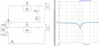
A parallel notch filter (cap and inductor placed in parallel, connected in series with the driver) is what the OP wants. It does not take much resistance to drop the Q of the notch filter - the ESR of the components may be enough. Adding a parallel notch filter will only increase the impedance, unless you accidentally make another resonance with some other existing part of the crossover.
In Xsim you need to check that trace smoothing is off and that the ESR of the components is realistic. Here I set all the components to 1mOhm ESR so you can see the ideal parallel notch filter with a high Q and deep notch. Then adding only 0.3ohm ESR to the inductor (I put it as an actual resistor component for clarity) drops the Q right down and gets it within range of what the OP wants. I had to re-tweak the value of the inductor and capacitor to get the frequency of the notch back to where it was previously.

The only 'tradeoff' is that the capacitor value is pretty high and all of the frequencies above the notch pass through that cap, so it needs to handle reasonable power. If you parallel a bunch of 100-200uF electrolytic caps you should be OK. Any excessive ESR of the inductor will add attenuation to frequencies below the notch and excessive ESR of the capacitor will add attenuation to frequencies above the notch. You can see that since I added the resistance to the inductor, there is a slight attenuation of bass below the notch. The ESR could also alternatively be in series with the capacitor instead, or a little bit on each component.
In Xsim you need to check that trace smoothing is off and that the ESR of the components is realistic. Here I set all the components to 1mOhm ESR so you can see the ideal parallel notch filter with a high Q and deep notch. Then adding only 0.3ohm ESR to the inductor (I put it as an actual resistor component for clarity) drops the Q right down and gets it within range of what the OP wants. I had to re-tweak the value of the inductor and capacitor to get the frequency of the notch back to where it was previously.
The only 'tradeoff' is that the capacitor value is pretty high and all of the frequencies above the notch pass through that cap, so it needs to handle reasonable power. If you parallel a bunch of 100-200uF electrolytic caps you should be OK. Any excessive ESR of the inductor will add attenuation to frequencies below the notch and excessive ESR of the capacitor will add attenuation to frequencies above the notch. You can see that since I added the resistance to the inductor, there is a slight attenuation of bass below the notch. The ESR could also alternatively be in series with the capacitor instead, or a little bit on each component.
Last edited:
That's cool. I'll have to try that in Xsim myself. Using a very large cap instead of a very large coil.
To me this looks like - don't use series notch filter in loudspeakers that will be used with lousy engineered amps.
It's more like "Don't do things that draw unnecessary current from your expensive electronics".
There is a common misunderstanding about how an amplifier actually works. They do not provide Power... they provide Voltage... how much current and thus the power consumed is entirely up to the load you put on them.
For Example:
If your power amp has a gain of 30 (which is typical) and you feed it 0.5 volts it is going to set it's output at 15 volts. Then it's feedback network is going to try to ensure it stays at 15 volts, as you increase the load currents the feedback will correct the amp to hold that 15 volts for you... and it will do that right up to the point of self-destruction.
So, at any given instant of time you are feeding your amplifier a voltage in to get a voltage out. Not power... not current... Voltage. Of course with music that voltage varies quite wildly with time but the behaviour is no different at 20khz than it is at 0 hz. Voltage in... Voltage out.
Wherever voltage meets impedance (or resistance) a current will flow. How much is dominantly a matter of the impedance. Ohms law describes this for us... I = E/R ... current equals Voltage divided by impedance. In fact, there has to be some impedance and thus some current to transfer the signal to the next stage. In pre-amps, phono, mic, line and other low power amps this current is often in microamps, resulting in mere milliwatts of power... but it is always there. So literally every amplifier has to be able to produce some output current or the whole thing just stops working.
It is also true to say that every amplifier has a limit to how much current it can produce. While in the case of signal amplifiers this is very small when we get to power amplifiers designed to feed single digit impudence loads, this current can be quite significant.
For example: a 100 watt amplifier designed to feed an 8 ohm load needs to provide ~29 volts ... which will cause 29/8 or ~3.6 amps of current.
Common sense design says it needs to do a bit better than that to provide a success margin, so a good design might reasonably be capable of 5 amps.
Now as I said above, what you do with that is entirely up to you. Obviously the goal is to get as much of that energy to your speakers as possible, in the name of efficiency and in the name of safety in not exceeding your amplifier's ratings.
A crossover network is inherently an inefficient thing. In the process of shutting down one driver while moving to the next with changes in frequency there are going to be some losses, it's inevitable. The more complex the crossover network, the worse this gets.
Every part you put in series wastes some power across itself. Every part you put across the leads routes some power to ground. This is unavoidable.
Now the question is at what level do these losses cease to be tolerable?
The answer is one of two cases... where the speaker becomes so inefficient as to demand ridiculous power -or- when it becomes so inefficient as to threaten to damage a power amplifier by exceeding reasonable design expectations.
Take a look a speakers of old ... the JBL L100, the Klipsch Heresy, and so on. Many of these speakers are still much sought after because of their exceptional sound and very high efficiencies often producing 92 or 93 decibels per watt. These speakers all have one thing in common... very simple crossovers, often just a coil for the woofer and a cap for the tweeters. Even the three way designs would most often have no more than half a dozen parts in their crossovers.
Now look at the way we design crossovers today. Some have 20 or even 30 components in them and look at the efficiency of them ... 84 and 83 db/w. This is not an accidental correlation. So much of an amplifier's energy is being wasted that a significant amount of loss is occurring... pushing the need for higher powered amps.
This is, in large part, attributable to two things ...
First, the trend towards smaller and smaller drivers. Be reasonable... you are not going to get room shattering bass from a 4 or 5 inch woofer, no matter how you tamper with it.
Second, and most importantly, the atrophy of technical knowledge. Where we once sat down and carefully calculated our circuits by hand, drawing them as we went and understanding why we used ever last part, now we sit down with simulators and build our circuits (crossovers in this case) after a fashion like playing with legos --just keep adding bricks until you get what you want-- with very little understanding of the underlying behaviour of each part. In fact, I keep running into people who can't tell me what a capacitor or a coil does or how it works... but they're happy to keep plugging them into a circuit none the less.
Much of what we see as credible speaker design, today, results from these two changes in the way things are done... and, trust me, even in high value commercial speakers... it shows.
Last edited:
I understand you are on a mission but you are getting your examples mixed up with your facts. Do you know the above figures are true in Zvus case? When giving help, if you're not transparent others might lose their perspective.Other than pulling 3 amps of current through your filter, increasing the current in your main inductor (and amplifier) to just over 6 amps at resonance. It might not kill your amp but it surely will run hotter. Not worth it for a 4db improvement.
Series bandpass filters used as notch filters in this way must be used appropriately. Did you know that it is suitable to put them directly across the amplifier terminals of a current amp? More importantly, the impedance within a circuit is not the Voltage source that you speak of, but some finite combination. What about examples to show the right ways to do it?
What about examples to show the right ways to do it?
In the OP's case he took the right way to do it... by moving his speakers out of the node excitation point.
There is no right way to put a shunt filter into the active passband of a crossover segment. Especially not at 70 or 110 hz where longer wavelengths lead to more heat.
There have been a couple of examples of stop filters that just might work but I would judge them to be wildly impractical because of the huge parts required.
Hence my initial "don't do this" response to the OP.
I will admit that I am quite puzzled that you guys appear not to realize how totally impractical your proposed solutions are... Of if you do, I'm seeing no hint the you are continuing with this solely as an intellectual exercise.
Anyone for tennis? (post #10 implying data needed for it to become other than an intellectual exercise).I'm seeing no hint the you are continuing with this solely as an intellectual exercise.
So, beyond saying "more data is needed" everything else is just spitballing?
Whew... that's going to take some getting used to.
Whew... that's going to take some getting used to.
Since 6V6 hasn't gotten back with any details or data, it remains an intellectual exercise. It would be nice to know more, but we probably won't.
If it came down to it I was going to consider a second stage. This example is crude but offers some options.
The lower (green) baseline has 300milliohms (like TMMs example). The top version has 1 ohm in each stage and still manages a higher Q (should that be necessary, however these tradeoffs could otherwise go toward a smaller inductor). Additionally, this resistance reduces the otherwise high current. It also means a smaller diameter inductor could be used.
The lower (green) baseline has 300milliohms (like TMMs example). The top version has 1 ohm in each stage and still manages a higher Q (should that be necessary, however these tradeoffs could otherwise go toward a smaller inductor). Additionally, this resistance reduces the otherwise high current. It also means a smaller diameter inductor could be used.
Attachments
Last edited:
- Home
- Loudspeakers
- Multi-Way
- Equalizing one channel only using capacitor?