Hi all!
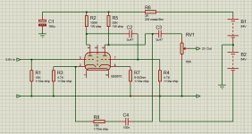
I have GE 5670 tubes, +/- 54v supply voltage and these scheme:

How to make it work together? 🙂
I have GE 5670 tubes, +/- 54v supply voltage and these scheme:
How to make it work together? 🙂
if you use the -54 volts as your 0 volts dc ground, then you have 108 vdc B+, will work but you will have to change the cathode resistors and plate load resistors...
how much gain are looking for?
how much gain are looking for?
I have power amplifier with ~2V input and +/- 54V voltage
Objective - not using additional power supply +200v for tubes if it possible and not will be worse
Objective - not using additional power supply +200v for tubes if it possible and not will be worse
Be careful.
If you forget that the amplifier input 'ground' is -54 volts with respect to Earth, and connect another earthed unit to it (input or output) you will short out the lower half of the power supply.
Can you post the Power Supply schematic as rayma requested?
It might be possible to re-configure it as a voltage doubler - that gets you near 200 volts.
I not have Power Supply schematic 🙁
Just wanna buy - this car Power Supply for Power Amp and tube preamp
Just wanna buy - this car Power Supply for Power Amp and tube preamp
It might be possible to re-configure it as a voltage doubler - that gets you near 200 volts.
Not very likely as the voltage doubler ground will be at -54 to the amplifier center tap ground. This will work only with galvanically isolated grounds.
Certainly doable, but if one has to ask how to do it best thing is not to do it. High chances of sparks flying.
Edit: only now noticed this is an smps. Without messing with it the only safe and easy option is to build a valve circuit powered by the +54v rail.
Last edited:
if you use the -54 volts as your 0 volts dc ground, then you have 108 vdc B+, will work but you will have to change the cathode resistors and plate load resistors...
This with a capacitor at the input and output should work...
I guess need something like this:

- R1 R2 resistors
On these scheme all ok - input and output with ground. How to make like that with my scheme?
One more and more simple scheme:

- but how to choose resistance values?
- R1 R2 resistors
On these scheme all ok - input and output with ground. How to make like that with my scheme?
One more and more simple scheme:
- but how to choose resistance values?
This would work better for the tube section, and no screwing around. It's cheap, too and it's clean enough that I use them even for phono stages.DC-AC Converter 12V to 110V 200V 220V 280V 150W Inverter Boost Board Transformer | eBay
Those are GARBAGE. Don't waste your money on it. They are noisy AF and they aren't isolated.
Last edited:
I have a few. All they're really good for is testing, they need very good filtering to remove the hash. I do have one I may throw on a flea amp build.
Need something like this:
but i don't know which cathode resistors should be and right my scheme or not. Help make corrections pls
You can use it basically as drawn with the following corrections:
1) decouple the -54V rail, at least copying what was done on the+54V one (2k resistor + 150uF cap; I´d use at least 1000 or 2200uF) because this is now the audio ground, as far as the tube is concerned.
2) add a series cap at the input, say 1Uf x 100V electrolytic, "-" side towards R1
Wonder why a mere 10k resistor was chosen for R1, would expect something like 220k instead.
Where did you pull this schematic from?
3) remember that audio signal will be applied to capacitor input and regular ground, do not use -54V as preamp ground.
4) output is already DC isolated by C3 BUT RV1 pot must be referenced to real ground also, not -54V
5) only to measure DC working point, you use -54V as tube ground and bias tube sections so plate voltage at idle sits roughly halfway between +54V and -54V
That this point is also near real ground is irrelevant.
6) to achive that, first power circuitb as-is, it might work properly; if not, vary cathode resistor values until you find the proper one.
7) you don´t want to add a power supply but you will still need to feed tube filaments.
How do you think you´ll achieve that?
8) what is the purpose of adding this anyway?
I have a few. All they're really good for is testing, they need very good filtering to remove the hash. I do have one I may throw on a flea amp build.
Very good filtering? I had a noise coming from my preamp that I couldn't quite trace. It was even present without the tubes installed. I was using one of those adjustable ones for 250V for a pair of 6E2 meters. Guess where the noise was from? LOL Switched it for one of the fixed voltages ones I linked (making it the third of those in the same PS) and no more noise!
Even with a 4.5H choke and a 47u caps, there's still ~30kHz hash and garbage on the scope... The only thing I'd use the adjustable one for is my prototyping setup or a tube tester 😛
(8) what is the purpose of adding this anyway?
the ability to use existing +-54 volt psu said the OP....
i think doable with the circuit as shown but the 6922/6H23/6dj8 works better here imho...
non feedback broskie ccda is as simple as it is very good....
(8) what is the purpose of adding this anyway?
No, that´s a way to achieving it, I want to know what´s the purpose of adding this preamp before the power amp.the ability to use existing +-54 volt psu said the OP....
- Home
- Amplifiers
- Tubes / Valves
- GE 5670 at +/- 54v supply voltage