No, that´s a way to achieving it, I want to know what´s the purpose of adding this preamp before the power amp.
single-cycle tube amplifier pros:
- the predominance of even harmonics (you do not get tired of listening to them) (. Also, very often the frequency response of such amplifiers begins to fall off at high frequencies due to the characteristics of the transformer and they do not sound so harsh.
- reinforce all this with a Class T amplifier, which itself plays sharply especially at high frequencies, but clearly and accurately transmits a signal
In general, the tube + T class I think will sound good
Where did you pull this schematic from?
It's from these kit:
Buffer 6N3 Tube Amplifier Preamp AMP Pre-Amplifier Matisse Kit

- and i trying to connect these cheme to +/- 54v and as result make these scheme:
- but is not correct, just show what i need.
apparently it’s better to use additional power supplies.
Those are GARBAGE. Don't waste your money on it. They are noisy AF and they aren't isolated.
But input with ground, output with ground, primary power supply with ground... - what pros of isolated power supply in this case if isolated ground will be connected to common ground via audio signal input and output?
Last edited:
This should work. Did it several times.
The amp behind this preamp must also have 0 or earth as ground for signal connection.
You can check this by measure between - power supply and earth input , should be -54v.
The amp behind this preamp must also have 0 or earth as ground for signal connection.
You can check this by measure between - power supply and earth input , should be -54v.
Attachments
Last edited:
But input with ground, output with ground, primary power supply with ground... - what pros of isolated power supply in this case if isolated ground will be connected to common ground via audio signal input and output?
You might not need the isolation. Sometimes I want to use the module as a negative supply for bias etc and these don't do that. The main problem is they are single ended and noisy AF...
If you still want one, I mail you one for the cost of postage.
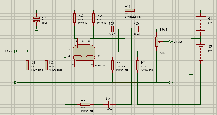
It's right? Do need some changes of resistor nominals?
-653v it's ok? Input signal is 0.5v sinus if it needed.
-653v it's ok? Input signal is 0.5v sinus if it needed.
Attachments
Last edited:
single-cycle tube amplifier pros:
- the predominance of even harmonics (you do not get tired of listening to them) (. Also, very often the frequency response of such amplifiers begins to fall off at high frequencies due to the characteristics of the transformer and they do not sound so harsh.
- reinforce all this with a Class T amplifier, which itself plays sharply especially at high frequencies, but clearly and accurately transmits a signal
In general, the tube + T class I think will sound good
Thought so but had to ask.
Sorry but you chose the wrong "tube flavoring" type circuit.
1) You show a VERY HIGH NFB circuit which will have inaudible harmonics, odd or even.
2) its frequencybresponse will be very flat, contrary to what you expect.
3) WHICH transformer????
4) given the high NFB, it will clip harsh, with sharp squarewave edges.
If you want to add tube flavour, just add a plain selfbiased single tube stage, with gain of course, not a cathode follower as shown in one of the schematics which has practically 100% NFB and is the flattest way a tube can be used.
If gain is too much, do not use NFB but passively attenuate its output.
EDIT: sorry buit your last schematic still has gross errors.
Won´t suggest corrections because anyway I am not suggesting you use it, but build a single triode stage instead.
In fact a starved plate tube , properly grounded (forget the -54V rail) and fed scarce 54V will provide gobs of tube flavour indeed.
I use that to add distortion and flavour to my own hybrid guitar amps, go figure.
Last edited:
3) WHICH transformer????
sorry, no transformer)
If you want to add tube flavour, just add a plain selfbiased single tube stage, with gain of course, not a cathode follower as shown in one of the schematics which has practically 100% NFB and is the flattest way a tube can be used.
If gain is too much, do not use NFB but passively attenuate its output.
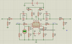
Like this? (GE5670 instead ECC88 or which one better?). How much mA on out will be? It will be enough?
Attachments
Last edited:
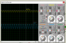
Done? Looks like ok 🙂
Input: sine 0.5v 1k
But it's ECC88. GE5670 ~same and will be ok in these scheme?
ps - original scheme (250VDC):

- Ia up to ~2ma
on my scheme Ia up to ~3ma, other shown voltages are ~same
Input: sine 0.5v 1k
But it's ECC88. GE5670 ~same and will be ok in these scheme?
ps - original scheme (250VDC):
- Ia up to ~2ma
on my scheme Ia up to ~3ma, other shown voltages are ~same
Attachments
Last edited:
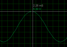
gain in my scheme little less:
in original scheme output - 7.1v (input 0.5v)
on my scheme output 5.3v (input 0.5v)
- it's ok for me
in original scheme output - 7.1v (input 0.5v)
on my scheme output 5.3v (input 0.5v)
- it's ok for me
Last edited:
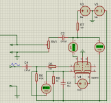
Like this? (GE5670 instead ECC88 or which one better?). How much mA on out will be? It will be enough?
Yes, something like that.
At first I thought you were still tweaking the original circuit 😀 but when enlarging the image (tired old eyes) I saw you are now using as suggested: plain triode gain stages, now 2 of them on the same board, each doing its thing unmolested 😎
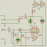
You may design it from datasheets of course, but since it´s both a single project and working outside the usual supply range, I would simply feed it the 54V available (you'll lose some of it with RC filtering, you might want to regulate it so low drop and high ripple rejection), keep the 33k plate resistor and vary the cathode one until plate voltage sits around, say, 35V DC.
You may even drive it to clipping and vary bias until you get roughly symmetrical clipping.
Once you found the proper cathode bias value, you substitute pot or resistance box with a fixed one.
Guess that´s what you were looking for 🙂
- Home
- Amplifiers
- Tubes / Valves
- GE 5670 at +/- 54v supply voltage