D2 and R4 take care of the positive feedback to ensure a safe start, that is not a problem
OK. I didn't study it in detail, but that caught my eye as it normally spells trouble. ;-)
Jan

Care to upload the asc file, please?
Why do you feed the reference from the dirty side instead of from the clean side?
Jan
View attachment biaspsu.asc
There is a cap across the zener in the real circuit and the zener is in fact a 10v voltage reference. If you put it on the other side it does not start I think. You may need a bleed resistor.
Why do you feed the reference from the dirty side instead of from the clean side?
Jan
There is a cap across the zener in the real circuit and the zener is in fact a 10v voltage reference. If you put it on the other side it does not start I think. You may need a bleed resistor.
Last edited:
View attachment 799615
There is a cap across the zener in the real circuit and the zener is in fact a 10v voltage reference. If you put it on the other side it does not start I think. You may need a bleed resistor.
Yes start needs to be verified. But if it does start, the benefits of a much quieter reference are worth it. Worth a try.
Jan
I used a reference as I need to output voltage to be more accurate - zeners have quite a spread.
If you replace R2 by a zener and D1, D3 by a resistor and make Q1 an NPN, it'll get better.
Jan,
Can you use the asc file and implement the changes you suggest, with the values you think should be better?
OK, this is the regulator I will use.
It's the best compromise in PSRR and impedance.
I changed the regulator's transistor, as the original 2SA is not available.
No parts affected the impedance response.
Only the base transistor cap in the cap multiplier improved things a little in the PSRR. But not much.
All other caps changed nothing.
Attachments
View attachment posreg.asc
Like that.
I trying to do something very similar 300v from 450v. I could not find pnp's high voltage but can use p-channel mosfet instead say.
https://www.onsemi.com/pub/Collateral/FQP3P50-D.pdf
I think a mica to220 kit is good for 500v.
Like that.
I trying to do something very similar 300v from 450v. I could not find pnp's high voltage but can use p-channel mosfet instead say.
https://www.onsemi.com/pub/Collateral/FQP3P50-D.pdf
I think a mica to220 kit is good for 500v.
One more update and some comments on other simulations I carried out.
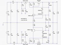
Even if this regulator was specifically designed, in output voltage, for a Luxman clone, it can be used in any other power amp to regulate high current stages.
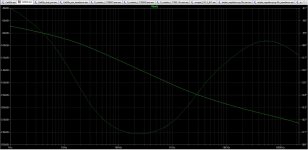
The simulated results are superb, even better than with the original LM317/337 I was originally planning to use. Both in PSRR and impedance.
A great help for improving PSRR were the input filters before the regulator itself: both the CRC and the capacitor multiplier.
Tests were also made replacing the CRC resistor with an inductor, but there were practically no differences in the PSRR curve, and the drop loss on both resistor and inductor was similar.
The largest drop, 3.5v, was from the CM, and I wonder if that can be diminished somehow. If not I think the input voltage will have to be 80v instead of 75v, jut to be safe on eventual AC line drops.
Included are the schematic and the asc file, so any comments or suggestions are welcome.
Even if this regulator was specifically designed, in output voltage, for a Luxman clone, it can be used in any other power amp to regulate high current stages.
The simulated results are superb, even better than with the original LM317/337 I was originally planning to use. Both in PSRR and impedance.
A great help for improving PSRR were the input filters before the regulator itself: both the CRC and the capacitor multiplier.
Tests were also made replacing the CRC resistor with an inductor, but there were practically no differences in the PSRR curve, and the drop loss on both resistor and inductor was similar.
The largest drop, 3.5v, was from the CM, and I wonder if that can be diminished somehow. If not I think the input voltage will have to be 80v instead of 75v, jut to be safe on eventual AC line drops.
Included are the schematic and the asc file, so any comments or suggestions are welcome.
Attachments
If you used a LM317/337 in the tracking pre-regulator configuration, would it be better than the CM?, probably cheaper too since that 2200uF hi voltage ecap is not cheap.
The pre-regulator has its own PSRR and so does the main regulator, they add up, so if the pre-reg is -70dB and so is the main then in theory you have -140dB PSRR.
cost wise, a lm317 is probably the same cost or lower than the 2200uF/80-100V ecap, BD139
add your component cost up and find out.
cost wise, a lm317 is probably the same cost or lower than the 2200uF/80-100V ecap, BD139
add your component cost up and find out.
It is in one of the datasheets (Old national LM117/LM317A/LM317
3-Terminal Adjustable Regulator) and in app notes, here are more links
LM317 tracking pre-regulator and current regulator
This thread describes it very well
Using 3-pin regulators off-piste: part 4
3-Terminal Adjustable Regulator) and in app notes, here are more links
LM317 tracking pre-regulator and current regulator
This thread describes it very well
Using 3-pin regulators off-piste: part 4
Using 3-pin regulators off-piste: part 2
shows that your CM is better at high freq rejection, unless you use an inductor in series for the pre-regulator, so the CM version may very well be a better solution overall if you need to add the indcutor.
A CM in front of the LM317 is good solution, if you have enough headroom.
shows that your CM is better at high freq rejection, unless you use an inductor in series for the pre-regulator, so the CM version may very well be a better solution overall if you need to add the indcutor.
A CM in front of the LM317 is good solution, if you have enough headroom.
- Home
- Amplifiers
- Power Supplies
- Using the LM317 with higher voltages