It could be that this IC works in reality but not in sim, but that would be strange, because it's a LT/ADI model.It was not me who selected that opamp. I got the asc file here.
Voltage Regulators for Line Level Audio. Part VI : The Jung Super Regulator - diyAudio
And you are right: replacing the IC makes things right.
Anyway, using a chopper-stabilized opamp for that task looks questionable: there are always chopping carrier residues present, even if the sim does not show them.
And for audio applications, such a DC accuracy is totally irrelevant
You have to decide for yourself where you want to look: wideband, zoom onto some spot frequency, a particular amplitude range....The impedance curve I'm getting is different from yours, but I think the problem is the Plot Limits data you are setting on the left.
Can you please show me what are the values I should load?
The main setting is the type of graph: for impedance linear is OK, log is also OK with the caveat that you didn't mess up the ACx, the rest is up to you: I didn't change anything in these values, but after the graph was plotted, I selected the Autorange to recenter the curve
For some reason, the LT1086 stopped regulating because the 40V input was too high, and this altered the parameters of the downstream post-regulator, but that is completely obvious: when something looks wrong, you need to look at the basic DC conditions, even if it is just by hovering over the nodes you examine.This is the curve I'm getting and this is the asc file for 30v I'm simulating.
I repeat once again, a dedicated thread is not the place to discuss such elementary issues: get a good on-line tutorial on LTspice, and if you have further, more specific issues, post them on the LTspice thread.
If you still have particular issues about a specific, circuit-related problem it is OK to post them in the thread, but you need to clear all basic problems first, because they are essentially unrelated to the circuit you discuss
OK. A question that is related to this thread, I think. Using or not using LT1086.
The original superregulator didn't use it, and if I'm not wrong even the boards Linear Audio sells do not either. So I can simply eliminate the LTs.
The idea for this thread was to compare simulation results from several regulators for PSSR, noise and impedance, and also to look at those curves available from actual measurements. Some of those curves we can get from Linear Audio.
But to do that I would need some help, and very much of it I already did get from you.
Learning how to do the simulations, as you propose, is something that would take some time, probably months or much more. That is if I can get help there too.
Wouldn't it be more practical to upload those files we still do not have and just make them ready for simulation? Then add all those that we already have and compare them all?
AFAIK there's no "LTSpice thread" here at DIYAudio. Just some threads here and there, but nowhere to take questions like how to simulate power supplies specs.
If you want to make purely numerical comparisons, they have to be fair, and you need to use a common denominator, for example an integrated regulator that will work at its best in all the situations.OK. A question that is related to this thread, I think. Using or not using LT1086.
The original superregulator didn't use it, and if I'm not wrong even the boards Linear Audio sells do not either. So I can simply eliminate the LTs.
The idea for this thread was to compare simulation results from several regulators for PSSR, noise and impedance, and also to look at those curves available from actual measurements. Some of those curves we can get from Linear Audio.
If an integrated regulator is already a supererreg by itself, any sim that doesn't use it is going to be disadvantaged.
You can also compare the merits of two solutions, based on their topology: for example, a single stage cap-multiplier will bottom at ~60dB PSRR due to Early effect, but common sense tells you that by cascading two such multipliers, you will be able to reach 120dB rejection, and that is going to be valid for any type of transistor.
You seem to think that I am an expert, or master in LTspice, but that's very far from being the case: I am reasonably fluent, and when I feel I am reaching my limits, I seek information and help, on the web first, then from specific sources like the Yahoo group, and finally from direct questions on a forum when no existing source can provide an answer (which is exceptional).But to do that I would need some help, and very much of it I already did get from you.
I don't think so: you don't need expertise in every aspect of LTspice, just a basic knowledge but when you need to deepen a particular aspect, you have to be able to find it, because it generally exists somewhere on the netLearning how to do the simulations, as you propose, is something that would take some time, probably months or much more. That is if I can get help there too.
I do not see exactly what you mean thereWouldn't it be more practical to upload those files we still do not have and just make them ready for simulation? Then add all those that we already have and compare them all?
Here it is :AFAIK there's no "LTSpice thread" here at DIYAudio. Just some threads here and there, but nowhere to take questions like how to simulate power supplies specs.
Installing and using LTspice IV (now including LTXVII). From beginner to advanced.
There might not be a specific answer to your specific problem, but there are probably useful elements, and the Yahoo group probably has answers to all your possible questions, although it is a PITA to use and search.
To summarize: "God helps those that help themselves", or in lay terms, learn to be autonomous.
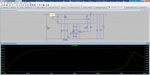
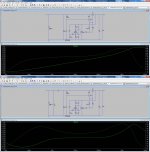
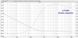
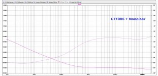
One comment I would like to add is because I have been doing some first impedance curves comparisons.
For now between the simpler Jung regulator, against the DeNoiser and even the original Luxman comparison. And I wonder how "real" they are.
Both the Jung and the DeNoiser hold a very low, absolutely flat zero impedance from 10Hz to 100KHz. In fact the DeNoiser holds flat up to 300KHz.
Now if we look at Linear Audio's actual measurements, made by Jack Walton, the Jung AD825 measures 0.001 Ohms @ 10KHz.
That more or less showed 0.0015 Ohms on the zoomed 10KHz area on our Jung simulation, even if with different chip.
But the impedance results for the DeNoiser is 67micro-Ohms, which I find difficult to believe might be so.
You can see the schematics by the curves, and I think the setup is right.
Any comments?
Attachments
I do not know the conditions of Jack's measurements: did he use Kelvin connections, was this possible with the circuits he tested, what is his measurement floor/resolution @10kHz?For now between the simpler Jung regulator, against the DeNoiser and even the original Luxman comparison. And I wonder how "real" they are.
Both the Jung and the DeNoiser hold a very low, absolutely flat zero impedance from 10Hz to 100KHz. In fact the DeNoiser holds flat up to 300KHz.
Now if we look at Linear Audio's actual measurements, made by Jack Walton, the Jung AD825 measures 0.001 Ohms @ 10KHz.
That more or less showed 0.0015 Ohms on the zoomed 10KHz area on our Jung simulation, even if with different chip.
I do not remember having made a measurement @10kHz, it was not recorded anyway, but I actually did a measurement for 1kHz and it was 15µΩ, so 67µΩ/10kHz is possible, in the right ballpark anyway:But the impedance results for the DeNoiser is 67micro-Ohms, which I find difficult to believe might be so.
D-Noizator: a magic active noise canceller to retrofit & upgrade any 317-based V.Reg.
Since the slope must be comparable for the sim and real circuits, I would say that the actual 10kHz impedance is 67*15/10 ~=100µΩ
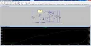
Some DeNoiser simulations comparisons for PSSR and impedance.
The only thing that changed was adding a CRC for one of the options.
Interesting.
How should I setup things for noise simulations?
The only thing that changed was adding a CRC for one of the options.
Interesting.
How should I setup things for noise simulations?
Attachments


I do not know the conditions of Jack's measurements: did he use Kelvin connections, was this possible with the circuits he tested, what is his measurement floor/resolution @10kHz?
I would have to read Jack Walton's again, but I would bet he did use Kelvin connections.
But I can also look and show the original WJ's measurements, where he did use Kelvin's connections, as it was the first place where I heard about them.
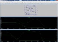
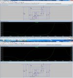
This a comparison between what I called the "simpler Jung" regulator, which is has no chip pre-regulator, as in my application the input voltage would exceed the LTs maximum.
The comparison is between using a single 2200uF filter input capacitor and using a CRC.
What was compared was PSRR and impedance, with and without the filter.
What did change with the filter was the PSRR response. The impedance was not affected, which I would like to know if it's correct or should be expected. If you look at both impedance curves absolutely nothing changed.
Attachments
So the simulations are OK?
That is very good to know.
Can you tell me how to proceed to simulate noise curves?
That is very good to know.
Can you tell me how to proceed to simulate noise curves?
Very interesting discussion I must say. What you have not revealed is what problems are you experiencing or is it a theoretical motivation.
Once your pre-amp is on the bench, that is the only time that you can tell where attention is needed. Theoretical simulation is all well but you have to regard component tolerances, temperatures, processes, variations, environmental influence, materials used, etc.
This can only be achieved practically. Every component of different manufacturers are really not a combined effort of all manufacturers sharing their knowledge and processes manufacturing a component that is identified by the same number. There are no universal models....
PCB layouts, induced noises, manufacturing processses, yes even your soldering ability. There are so many things that you can only achieve in a practical application, using the components of a particular manufacturer.
I have in the past, (not necessarily audio designs) had high expectations of a particular transistor, had very different results from the "same" component from another manufacturer and in cases not performed as anticipated or simulated.
I have used MicroCap since 1994 and it has been a good guideline but if this is to be a product specifying components in particular is necessary, then your practical testing and verification is essential.
Imagine an atomic bomb fuse was going from simulation to production? If you are making something for your own use and want to play around, simulating outcomes is like computer games you get hooked on it, completely. Once you have proved your design is working, the ballpark outcome using whomever's great models are is good enough for a pleasing result and the feeling that you have designed it from scratch and is probably most gratifying of all.
Anyway, build it, the proof of the pudding is to enjoy your creation, you will eventually get tired of it and design a new product that may be better more pleasurable, whatever.
If you cannot specify why a regulator needs an output impedance of 1u Ohm or 100 u Ohm for any valid reason then what is the point.
Remember your countryman Uncle Charley. He built thousands of prototype amps to verify that it did what it was supposed to do.
Last edited:
Very interesting discussion I must say. What you have not revealed is what problems are you experiencing or is it a theoretical motivation.
I'm not experiencing any problems. I'm just building some low noise RIAA preamps, and I want the best PS I can get. And the specs of that power supply are PSRR, noise and impedance.
The latter is less familiar to most people, and it was The Audio Amateur the first place where impedance was identified as one of the most important characteristics on a supply.
Audio amplifiers work very hard to replicate the output waveform to match the input waveform, and a low impedance power supply helps by providing enough current to avoid distorting the waveform during demanding audio.
Simulation is just a very first stage, and I am now trying to parallel the sim results with actual measurements. In this case provided by Walt Jung and by Linear Audio.
Add a .noise directive, and follow the instructions you find on the net, here for example:Can you tell me how to proceed to simulate noise curves?
Noise Analysis Using LTspice Tutorial - Technical Articles
YouTube
Etc.
For a power amp yes this affects the max output level if nothing else - but many power amp supplies are transformer/rectifier/capacitor, so the voltage droop is the relevant parameter reallyI'm not experiencing any problems. I'm just building some low noise RIAA preamps, and I want the best PS I can get. And the specs of that power supply are PSRR, noise and impedance.
The latter is less familiar to most people, and it was The Audio Amateur the first place where impedance was identified as one of the most important characteristics on a supply.
For an RIAA preamp the output needed is measured in mA and the voltage headroom is substantial, its trivial to provide enough current sourcing/sinking ability for a preamp.Audio amplifiers work very hard to replicate the output waveform to match the input waveform, and a low impedance power supply helps by providing enough current to avoid distorting the waveform during demanding audio.
The PSRR of the amp interacting with the supply's output impedance might be an issue if the PSRR is poor and the supply has a large impedance. If you want to be able to power arbitrary amps then yes, sometimes the supply impedance will matter (at LF, the decoupling caps will take care of the HF impedance one hopes)
Simulation is just a very first stage, and I am now trying to parallel the sim results with actual measurements. In this case provided by Walt Jung and by Linear Audio.
OK, I'm trying to figure out how accurate or realistic are the results we get from LTSpice simulations.
The reference I'm using for that, which most will probably agree with, are the measurements Walt Jung did in 1995, in The Audio Amateur magazine, that were published in issue 2/95.
They are available here, in pdf.
https://refsnregs.waltjung.org/Regs_for_High_Perf_Audio_1995.zip
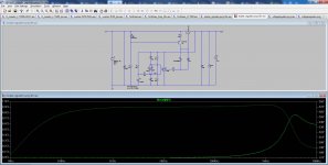
Let's start with the impedance curves for 3-legged regulators. In our case we will concentrate on the LT1085, which is the one I can simulate.
I adjusted the horizontal and vertical parameters as best as I could, from 20Hz to 200KHz, which is what Walt used.
The reference I'm using for that, which most will probably agree with, are the measurements Walt Jung did in 1995, in The Audio Amateur magazine, that were published in issue 2/95.
They are available here, in pdf.
https://refsnregs.waltjung.org/Regs_for_High_Perf_Audio_1995.zip
Let's start with the impedance curves for 3-legged regulators. In our case we will concentrate on the LT1085, which is the one I can simulate.
I adjusted the horizontal and vertical parameters as best as I could, from 20Hz to 200KHz, which is what Walt used.
Attachments

Last edited:
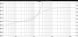
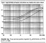
> Walt's and simulated curves for LT1085
If you put your sim graph in LOG scale it will look a lot like Walt's.
How many inches of wire is 10 milliOhms?
Ah: Copper Wire Resistance and Inductance Calculator
So 10mOhms is a foot of #20, so you don't have to mount your low-R supply right ON your phono preamp, can even put it outside the cage.
I have been trying to compare PSRR on different regulators, which I intend to post here.
Very interesting.
1) One thing I wonder, which was raised on another thread, is how low can considered realistic or feasible.
In that case I was playing with an LT3042 PSSR curve, which got very low.
The question that was raised was "-196dB is not creditable in a real-world circuit. It "might" happen through lucky cancellation. Or expect to real-life measure (or hear!) it.
>100dB is creditable, in a simulation, although real life parasitics will spoil this."
What do you think of this?
2) Is it a descending curve, that does start at say -70dB @ 10Hz and steeps down to -156dB @ 20KHz, better or worst than one that is almost flat at -120dB on the same frequency range. Flatness is better than getting to a lower point?
3) Isn't it more realistic to limit the frequency range between say 1Hz and 220KHz, instead of showing or caring for where the curve goes at 1MHz or 10MHz?
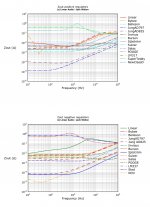
OK. These are the PSRR simulated curves I got from six different regulators.
I can provide the asc files, if someone wants them.
But I had to use a CRC filter at the input of each regulator to get really good results.
The voltages being low, in this case 30v, the 2200uF chosen capacitors won't be large.
Pity I don't know how to put all the curves in the same graph, to make the comparison easier.
Let's hope you find these comparisons interesting. If you do I can compare impedances too.
Attachments
-
 Low voltage regulators#1 - PSRR.jpg300.6 KB · Views: 245
 -
 Low voltage regulators#2 - PSRR.jpg238.7 KB · Views: 242
 -
 Low voltage regulators#3 - PSRR.jpg243.4 KB · Views: 118
 -
 Low voltage regulators#4 - PSRR.jpg239.2 KB · Views: 120
 -
 Low voltage regulators#5 - PSRR.jpg247.6 KB · Views: 122
 -
 Low voltage regulators#6 - PSRR.jpg353.7 KB · Views: 123
- Home
- Amplifiers
- Power Supplies
- Looking for a good power supply for a RIAA preamp