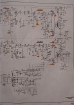
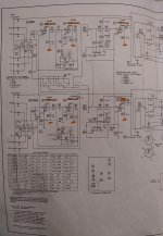
Hi guys, I've been working on this Sherwood S-5000 ii. I've been going through it bit by bit. So far I've replaced the coupling caps, restuffed the cans, cleaned and checked the pots, checked voltages and resistances for the power and preamp tubes, and so far everything looks good. I've powered up to 105V on a variac and I get sound out of the left channel only. I've played tube roulette ( the power tubes are a new matched quad ) just to be sure its not a tube and nothing changes. I haven't checked the transformers because I don't know how yet but I did try both the 8 and 16 ohm outputs to see if maybe just the 8 ohm winding was out, but neither worked. Can someone turn me in the right direction as far as how to troubleshoot where the issue could be stemming from? Also, what is the correct way to test the output transformer to be sure that's not the issue. I can say that the voltages on the primary appear to be fine. Schematic is attached.
Thanks
Thanks
Attachments
Did it work before the overhaul? Any audible hum in the bad channel?
Do you have a scope and signal generator, or only a DVM?
Do you have a scope and signal generator, or only a DVM?
Last edited:
I have no history on it. It was an eBay purchase with the intent of rebuild. I wanted to do the base minimum before firing it up for the first time. All I have is a dvm and lots of time.
I have no history on it. It was an eBay purchase with the intent of rebuild. I wanted to do the
base minimum before firing it up for the first time. All I have is a dvm and lots of time.
Ok, set the balance control to its center, and the function switch to "CH 1+2".
Is there sound in both channels now?
If yes, try turning the tape monitor switch on and off several times, or clean it.
Same for the input selector switch.
If no, the problem should then be in the power amplifier.
Sherwood S-5000 - Manual - Vacuum Tube Integrated Amplifier - HiFi Engine
Last edited:
A simple Signal Tracer going from source input to output along the signal chain would have this narrowed down in less than ten minutes.
🙄
🙄
A simple Signal Tracer going from source input to output along the signal chain would have this narrowed down in less than ten minutes.
🙄
Unfortunately as I stated before I don't own one and don't have acces to one at the moment.
Unfortunately as I stated before I don't own one and don't have acces to one at the moment.
With all due respect, I'll repeat my comment from that other thread about this unit...
Which I'm sure you must have read.
"As for lacking the proper test equipment, a multimeter is not sufficient.
It's like asking a car repairman to change the spark plugs and change the oil with just a screwdriver.
It ain't gonna happen."
So with that said, again, attempting to do service on that Sherwood without the proper set of "tools" is only foolish, frustrating, and generates endless threads, posts, and problems, not to mention you having a lack of troubleshooting skills. (which you already stated previously).
While this is a forum for all types of "learners", ignoring facts and suggestions that are posted to help, isn't the way to success.
And I'm pretty certain that most all people like to be successful in their endeavors, with the exception of people just wasting their time.
I've given my recommendations, but I feel they're tossed to the wind.
Good luck with that thing, I'm outa here.
...
I haven't checked the transformers because I don't know how yet but I did try both the 8 and 16 ohm outputs to see if maybe just the 8 ohm winding was out, but neither worked. Can someone turn me in the right direction as far as how to troubleshoot where the issue could be stemming from? Also, what is the correct way to test the output transformer to be sure that's not the issue. I can say that the voltages on the primary appear to be fine. Schematic is attached.
Thanks
To check the output transformer(s) switch off and unplug the amp. Leave it for 20 minutes so the capacitors discharge.
Now check the secondary winding with your multi-meter on a low ohms range, no speakers connected, check the resistance from the 'G' terminal to each of the 4/8/16 ohm taps. You will get very low readings if all are well. (0.3 ohms per section on the schematic.)
Now check the primary. With your meter set on 2k ohms (or similar) locate the 'Red' wire from the transformer. Probably the junction of R101 and R102.
Next follow the 'Blue' wire. At pin 3 of the output tube. Measure the resistance between the red and blue wires. The schematic says 170 ohms.
Do the same for the 'Brown' wire from the transformer. Again pin 3. Red to brown should be 195 ohms from the schematic. Chances are they are both fine.
Next answer the question, is there any sound at all from the faulty channel? Hissing fizzing, hum anything. After that you can move on to finding which section the problem is in...
With all due respect, I'll repeat my comment from that other thread about this unit...
Which I'm sure you must have read.
"As for lacking the proper test equipment, a multimeter is not sufficient.
It's like asking a car repairman to change the spark plugs and change the oil with just a screwdriver.
It ain't gonna happen."
So with that said, again, attempting to do service on that Sherwood without the proper set of "tools" is only foolish, frustrating, and generates endless threads, posts, and problems, not to mention you having a lack of troubleshooting skills. (which you already stated previously).
While this is a forum for all types of "learners", ignoring facts and suggestions that are posted to help, isn't the way to success.
And I'm pretty certain that most all people like to be successful in their endeavors, with the exception of people just wasting their time.
I've given my recommendations, but I feel they're tossed to the wind.
Good luck with that thing, I'm outa here.
"I'm outa here" Good riddance!
This is a DIY forum bub. This isn't a professional tech, guru, god-complex forum. This is exactly the place where newbies come to learn so if you don't like my threads of "endless questions" them by all means don't read them. The only take home that I can extrapolate from your "sage wisdom"
 is that since I don't have the tools or know-how then I shouldn't be working on it...which means that the only option I have is to take it to a professional technician. Well guess what, the nearest guy is 100 miles from me, and he is backed up for months. You have offered no "real" solutions to my questions. Taking it to someone is no option.This is a project for me, a hobby, its not the end the world if I blow it up or don't fix it. The whole reason I do these things is to learn a new skill and hopefully end up with something I can be proud of. Yes I've admitted that I'm a novice but this is how one learns, isn't it? This is how an person develops troubleshooting skills. How did you learn? Did you come out of the womb with an umbilical cord attached to an oscilloscope? Nope, you started some where as well. Making mistakes along the way, and for sure someone was there to guide you.
Thanks but no thanks.
One missing safety feature of this amp . . .
There are no bleeder resistors.
That's a valid concern for sure. I've been keeping an eye on the caps and they dissipate pretty quickly. Within a minute there is nothing above 10 V.
Ok, set the balance control to its center, and the function switch to "CH 1+2".
Is there sound in both channels now?
If yes, try turning the tape monitor switch on and off several times, or clean it.
Same for the input selector switch.
If no, the problem should then be in the power amplifier.
Sherwood S-5000 - Manual - Vacuum Tube Integrated Amplifier - HiFi Engine
When I set the function switch to "Ch 1+2" I get sound out of only the left speaker, but it is getting signal from both inputs as I use a "left-right" audio track. I know the inputs are working.
To check the output transformer(s) switch off and unplug the amp. Leave it for 20 minutes so the capacitors discharge.
Now check the secondary winding with your multi-meter on a low ohms range, no speakers connected, check the resistance from the 'G' terminal to each of the 4/8/16 ohm taps. You will get very low readings if all are well. (0.3 ohms per section on the schematic.)
Now check the primary. With your meter set on 2k ohms (or similar) locate the 'Red' wire from the transformer. Probably the junction of R101 and R102.
Next follow the 'Blue' wire. At pin 3 of the output tube. Measure the resistance between the red and blue wires. The schematic says 170 ohms.
Do the same for the 'Brown' wire from the transformer. Again pin 3. Red to brown should be 195 ohms from the schematic. Chances are they are both fine.
Next answer the question, is there any sound at all from the faulty channel? Hissing fizzing, hum anything. After that you can move on to finding which section the problem is in...
Thanks. Will do and will post the results. Also, there is no sound whatsoever from the faulty channel.
"I'm outa here" Good riddance!
Yes I've admitted that I'm a novice but this is how one learns, isn't it? This is how an person develops troubleshooting skills. How did you learn? Did you come out of the womb with an umbilical cord attached to an oscilloscope? Nope, you started some where as well. Making mistakes along the way, and for sure someone was there to guide you.
Thanks but no thanks.
LOL!
Thanks for the snotty reply, it's typical from frustrated "novices".
I didn't rely on internet blogs, because the internet wasn't born yet., thus my "schooling" came from instructors and textbooks in classrooms devoted to training us "professional techs".
We wern't allowed to "make mistakes".
We didn't jump into projects over our heads by ignoring proper protocall.
And the snotty creeps that did, usually failed the course.
LOL!
typical from frustrated "novices".
We wern't allowed to "make mistakes".
We didn't jump into projects over our heads by ignoring proper protocall.
And the snotty creeps that did, usually failed the course.
I think that is one of the most horrible arrogant replies I ever saw.
The guy asked for help, not to be told how clever you think you are.
You can learn to spell - protocol, is what you wanted to say???
So what? What is this "protocol" this guy is supposed to know about.
I dunno what age you are, but if I were my 14 year old daughter, wanting to learn a little electronics, even to make a crystal set for fun, I would look quite carefully at the kind of answer you just made, and be put off for life! 🙄
It's quite normal to get your head bitten off at some stage - don't worry about it and keep posting. You are going to need something which measures signal through the circuit if you are going to find the issue.
Last edited:
When I set the function switch to "Ch 1+2" I get sound out of only the left speaker, but it is getting
signal from both inputs as I use a "left-right" audio track. I know the inputs are working.
Then it seems the problem is in the power amp section, after the volume control.
That considerably simplifies things. If all the tubes light up and work, then R45 could
be open, is there 0.7VDC across it? If so, it is ok. Then one of the capacitors C21, C22, C23, C25
could be open circuit. You could try bridging each, one at a time, with a suitable capacitor
such as 0.1uF at 400VDC. For each, one at a time, turn off the amp, allow discharge,
tack solder the cap in parallel with the existing one, and turn on power.
The power supply is ok since one channel works, although a bad connection could still remove voltage.
Many people have to troubleshoot with limited equipment, but a little thought can compensate for this.
Last edited:
It's quite normal to get your head bitten off at some stage - don't worry about it and keep posting. You are going to need something which measures signal through the circuit if you are going to find the issue.
Thank you for the support. Every forum seems to have one of those. I'll get it figured out one way or they other.

I think that is one of the most horrible arrogant replies I ever saw.
The guy asked for help, not to be told how clever you think you are.
You can learn to spell - protocol, is what you wanted to say???
So what? What is this "protocol" this guy is supposed to know about.
I dunno what age you are, but if I were my 14 year old daughter, wanting to learn a little electronics, even to make a crystal set for fun, I would look quite carefully at the kind of answer you just made, and be put off for life! 🙄
Cheers 6V!
Then it seems the problem is in the power amp section, after the volume control.
That considerably simplifies things. If all the tubes light up and work, then R45 could
be open, is there 0.7VDC across it? If so, it is ok. Then one of the capacitors C21, C22, C23, C25
could be open circuit. You could try bridging each, one at a time, with a suitable capacitor
such as 0.1uF at 400VDC. For each, one at a time, turn off the amp, allow discharge,
tack solder the cap in parallel with the existing one, and turn on power.
The power supply is ok since one channel works, although a bad connection could still remove voltage.
Many people have to troubleshoot with limited equipment, but a little thought can compensate for this.
Got it, thanks... I'll check those out and get back to you.
- Status
- Not open for further replies.
- Home
- Amplifiers
- Tubes / Valves
- no output right channel Sherwood S-5000ii