Hi people,
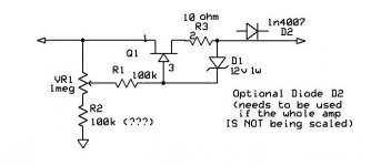
So I fixed my amp, now I have a new problem regarding VVR. I'm using the schematic attached I found online. It looks simple enough. Only difference I made was to use an IRF840 mosfet. I turned the amp on with a variac to start with and with a HT of 160v I was only getting a max output of 46v. Any higher than a HT of 200v it sounds as if something is sparking. I used and IRF840 in the effect loop so I would assume it's suitable. Anyone have any idea on what's going wrong?
So I fixed my amp, now I have a new problem regarding VVR. I'm using the schematic attached I found online. It looks simple enough. Only difference I made was to use an IRF840 mosfet. I turned the amp on with a variac to start with and with a HT of 160v I was only getting a max output of 46v. Any higher than a HT of 200v it sounds as if something is sparking. I used and IRF840 in the effect loop so I would assume it's suitable. Anyone have any idea on what's going wrong?
Attachments
What's the B+ voltage in your amp?...an IRF840 mosfet.
The IRF840 is good for 500 V maximum, and several amps of current (but not both at the same time.) With semiconductors it's wise to leave a significant safety margin, so if your B+ is well over 400 volts DC, you may be cutting your margins a little thin. (But that is probably not the cause of your current problems.)
Questions:with a HT of 160v I was only getting a max output of 46v. Any higher than a HT of 200v it sounds as if something is sparking.
1) What size is the pot you're using? Miniature pots are not rated to have several hundred volts across them. That could be the cause of the sparking you're hearing - it might be inside the pot.
2) How is the IRF840 mounted? I presume you're aware that the metal mounting tab is "live" at B+ voltage. It can be mounted on a metal heatsink directly, but only if that heatsink is electrically isolated from the chassis. (The heatsink will be "live", and dangerous.)
Better to mount the MOSFET to heatsink or chassis with an electrically insulating (but thermally conducting) insulator pad.
In any event, I hope you took precautions to keep fingers away from that MOSFET mounting tab. If not, please do! Build a plastic box with ventilation holes around it, put on a "Danger! High Voltage" label, make it impossible to touch by accident.
3) Have you double and triple-checked your MOSFET connections? The gate is not the middle pin, and source and drain are not interchangeable.
If those questions don't lead you to the source of the problem, a couple of clear photographs might help. If that still doesn't solve the mystery, it's back to the DMM for more voltage readings. Let's take one step at a time, though.
-Gnobuddy
B+ is 300v on 234v in.
1. Pot is 1meg .5w not sure the distributed sells these same pots anymore but i'll have to find a datasheet.
2. Mosfet is mounted right on the chassis with a thermal pad.
3. Quadruple checked connections. Wired the same as the mosfet source follower in the effect loop.
I'll post a picture and more readings when I get in the workshop
On a side note I'm beginning to think this amp is cursed as the bass control isn't working either... Pot is fine just about to change the capacitor
I disconnected the mosfet drain as seen and the pot works fine. So it's the mosfet that is the issue. I have an IRFBE30PBF 800v 4.1a rating might try it instead.
I've bought MOSFETs online from a vendor who put them in ordinary plastic Ziploc bags - every MOSFET was already dead by the time it got to me.So it's the mosfet that is the issue.
If you bought your MOSFET(s) from a more knowledgeable electronics vendor, they should have arrived in a static-safe conducting bag. But did you handle it/them with static-safe precautions in place? You can blow a MOSFET simply by picking it up in your fingers. You need to be wearing a grounded wrist-strap, and working on a grounded conductive surface.
Please note that the grounded wrist-strap and grounded work surface are essential for working with MOSFETs, until they're soldered into a properly designed circuit. But those same two items - grounded wrist-strap and work surface - are deadly for working with valve equipment, where they hugely increase your chances of being electrocuted.
For me it takes a deliberate mental effort to remember to switch from one set of safety precautions to another, when I switch from working on low-voltage static-sensitive electronics to high-voltage valve stuff.
-Gnobuddy
I sympathize with your frustration. But building an amp is engineering, not witchcraft....I'm beginning to think this amp is cursed...
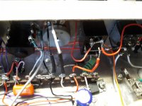
The problem is, the engineering is bad. You have the parts crammed tightly together, output valves right next to input valves, with a rats-nest of wires threaded randomly through the mess, with absolutely no attention paid to layout or its consequences. Frankly, it's a miracle this amp ever stopped oscillating long enough to work for a second. 🙁
I would count it as a learning experience. Now you know a number of things to avoid when you build your next amp.
-Gnobuddy
Changing the mosfet did stop the sparking sounds but it's still way under voltage. I didn't realise mosfet were so sensitive. I've used them before without said precautions and they have worked. Maybe I've been lucky.
Two things to check:...still way under voltage.
1) Measuring with your DMM at the pot wiper, does that get all the way to full B+ when you turn the pot to maximum? It should, otherwise the pot is defective or mis-wired.
2) When the pot is turned to its max setting, what voltage do you have across the zener diode (DMM set to DC volts, red DMM lead on MOSFET gate, black DMM lead on zener diode where it meets the 10 ohm resistor?)
You should read several volts here, maybe up to 10 V. If you read well under one volt instead, the zener diode may be wired backwards. If this is the case, the zener will stop the MOSFET from ever turning on, and that will cause low B+ out of the VVR.
You're definitely a lucky guy! 🙂I didn't realise mosfet were so sensitive. I've used them before without said precautions and they have worked. Maybe I've been lucky.
Some MOSFETs have protection diodes built right into them, and those are more likely to survive mishandling. But all MOSFETs are inherently static sensitive, and need handling precautions.
The reason is that MOSFETs have a microscopically thin layer of silicon dioxide - glass - insulating the gate from the FET channel. Too much voltage on the gate blows a microscopic hole right through this insulating layer, as though a very tiny bolt of lightning struck it. This kills the MOSFET dead.
Because the glass layer is so very thin, it doesn't take much voltage to do this - twenty volts might be more than enough. Our bodies easily build up several hundred, even several thousand, volts just by walking across a carpet, or dragging your sleeve across the couch. If you touch the MOSFET with all that static charge on your body, it kills the MOSFET.
That's why the grounded work surface (so the MOSFET is at zero volts), and the grounded wrist-strap (so your body is at zero volts.) Now you can touch the MOSFET without blowing it up.
-Gnobuddy
Ok so I got it working (blown zener) but it's still being weird. The amp works perfectly fine when the vvr is set to minimum to 150v, but then it starts oscillating and humming again, up until 270v where turning it up more causes it to jump down1 to 245v it then works as normal. Is it just the pot?
You can blow a MOSFET simply by picking it up in your fingers. You need to be wearing a grounded wrist-strap, and working on a grounded conductive surface.
... But those same two items - grounded wrist-strap and work surface - are deadly for working with valve equipment, where they hugely increase your chances of being electrocuted.
... The problem is, the engineering is bad. You have the parts crammed tightly together, output valves right next to input valves, with a rats-nest of wires threaded randomly through the mess, with absolutely no attention paid to layout or its consequences. -Gnobuddy
When I first attempted to install VVR into my guitar amps I had failure after failure of the MOSFET due to static that I initially didn't eliminate properly with a grounded anti-static pad. I had the strap and pad, but didn't ground the pad properly. Once I learned that expensive lesson, my installations went without problems.
Great caution about using the strap and pad with powered up tube gear.
Another problem I had with my first installation attempt was noise caused by plaiting the wires connecting the MOSFET instead of keeping the leads shorter and parallel. The maker of the VVR kit caught my mistake in photos.
The amps I have built have been higher gain TW and other circuits that are quite sensitive to wire length and layout. Less wire is good, in my experience. Who needs antennas and stray capacitance inside their a amps?
See my output is fine except for on 1/4 of the pot. I've got a new pot on the way. I'l see if that works
If you haven't seen it, follow some of the tips here: VCB/VVR installations - cathode biased only
and here: InfoCentre - VCB/VVR kit (cathode biased amps)
I assume you're building it like this but with a differing MOSFET?
and here: InfoCentre - VCB/VVR kit (cathode biased amps)
I assume you're building it like this but with a differing MOSFET?
An externally hosted image should be here but it was not working when we last tested it.
The ones I have used were NTE2973 - much more capacity (and $$$) than the ones you are using, yet they still get HOT.
I have seen these recommended as less expensive but with lower capacity. They may be similar to yours, but you can check.
STW15NK90Z
I have seen these recommended as less expensive but with lower capacity. They may be similar to yours, but you can check.
STW15NK90Z
Last edited:
My guess is it's the same problem that's been plaguing you for this entire thread: unwanted oscillations due to problematic layout and wiring.It's just at 150-245v.
The voltage gain of a vacuum tube changes with the applied B+ voltage. As you twiddle B+ with your VVR, each gain stage in your circuit experiences variations in gain, output impedance, and frequency response.
That being the case, it's my guess that it just so happens that the whole circuit bursts into oscillation for some range of B+ that you're dialing in.
There's a simple way to test my hypothesis: disconnect the VVR output from your amp. Put a dummy load (resistor) on the VVR output instead, something that draws roughly the same current as your amp would. See if the VVR behaves properly with the dummy load.
If the VVR is fine with the dummy load, and the problems come back when you connect the amplifier instead of the dummy load, then you know the problem is the amp, and not the VVR.
-Gnobuddy
- Home
- Live Sound
- Instruments and Amps
- VVR problems