That is goin gto be an ML-TL. but given the braces oriented the wrong way and not taking advantage of a driver offset points me towards thinking they did not take into consideration.
Does the power supply have a voltage/current adjustment? If it does, at what setting do they think that box is right. Althou didn’t you say you were getting the field coil? The SWR250 is not such.
I’d be starting from 1st principals.
dave
Does the power supply have a voltage/current adjustment? If it does, at what setting do they think that box is right. Althou didn’t you say you were getting the field coil? The SWR250 is not such.
I’d be starting from 1st principals.
dave
I didn't like the looks of the box either, sorry just a first impression. I would also redesign the frontage - the baffle shape/size around the driver and rounding, but that's something I'm partial to. There should be some directivity alleviating this at higher frequencies, so rounding shouldn't be small, but it is unclear as the spec sheet shows only an axial plot. (Very nice plot by the way, and good looking driver.)
There is an error on the reflex plan. 112 top middle vs 324 bottom (112 is half of 224, simple mistake or ?)
There is an error on the reflex plan. 112 top middle vs 324 bottom (112 is half of 224, simple mistake or ?)
|xxxxxxxxxx | upper brace (left side bonded)
| SSSSSSS | shear layer
| xxxxxxxxxx| lower brace (right side bonded)
I believe Earl Geddes said something to the effect that this was an extremely effective dampener as the displacement in the shear layer is maximized.
Yes, a similar method has been advocated by Geddes. I plan to give it a try in my next cab, it seems like it'd be pretty easy and effective and could perhaps allow for some really nicely performing lightweight solutions.
Good to know some of my memory is intact! 🙂 I've been curious to try it as well, but my last and next builds were a mltl and will be a tqwtp, where the internal structure forms the tube, so I don't want lossy walls there. Let us know how it goes!
It doesn't work that way. These walls are as good as building them with the wood you use. Only their movement is damped. Without the CLD, that movement would still happen only it would mean more sound outside the box.so I don't want lossy walls there.
AllenB -- I think you've lost me? With the arrangement I drew above, there's no rigid mounting between the two walls, making the two respective sides of the brace structure pretty flexible to forces normal to their bonding face (or shear plane if that makes more sense). We don't have isobaric conditions in these pipe-based alignments so I'm worried about the respective walls "breathing" near pipe resonance.
I could be out to lunch in practice, which case I'll happily concede to your assertion. 🙂 I guess I should mock one up to see just how flexible it truly is to forces normal to its bonding face. Obviously I'm not worried about structural failure but damping of pipe resonances. What you're suggesting is that this structure is quite stiff as well.
I could be out to lunch in practice, which case I'll happily concede to your assertion. 🙂 I guess I should mock one up to see just how flexible it truly is to forces normal to its bonding face. Obviously I'm not worried about structural failure but damping of pipe resonances. What you're suggesting is that this structure is quite stiff as well.
Oh, you were talking more about the brace. I recall Earls motivations. He was concerned about the walls radiating sound outward, interfering with the direct sound from the cone, thus changing directivity among other things. Fairly standard I think.
Then there is his assertion that each side of a CLD should be the same thickness. To me this says that they would share the bending to some degree, (so no hidden surprises like the outside wall not moving and the inside wall lossy).
Then there is his assertion that each side of a CLD should be the same thickness. To me this says that they would share the bending to some degree, (so no hidden surprises like the outside wall not moving and the inside wall lossy).
You might still be right, even in the case of this bracing structure. 🙂 Sorry for being unclear. Equal side thickness means that the greatest flex occurs right in the shear layer and thus dampening is maximized.
high grade plywood has good and cool look but all sheets i find at my local store are always warped (unless they are very thick), makes it impossible to lay flat on the table saw, i find mdf and particle board much more dimensionally stable
high grade plywood has good and cool look but all sheets i find at my local store are always warped (unless they are very thick), makes it impossible to lay flat on the table saw, i find mdf and particle board much more dimensionally stable
Find a better supplier-truly good ply is very flat and stable. Baltic Birch or Appleply are two good options.
That is goin gto be an ML-TL. but given the braces oriented the wrong way and not taking advantage of a driver offset points me towards thinking they did not take into consideration.
Does the power supply have a voltage/current adjustment? If it does, at what setting do they think that box is right. Althou didn’t you say you were getting the field coil? The SWR250 is not such.
I’d be starting from 1st principals.
dave
Hi Dave, back from the dead - flu.
Yes, I ordered the field coil, but I "assumed" the cabinet for the non-FC would work for either. is that a bad assumption?
Yes, there are 4 power settings on the power supply. I know that when power is increased the volume goes up but beyond that I don't know why the need for different power settings.
Quote: Re: Field Coil speakers- "I know that when power is increased the volume goes up but beyond that I don't know why the need for different power settings."
Those things are just another "gimmick" designed to keep cash flowing - from your wallet to their accounts.
Usually with wild claims of some kind of "special" performance.
AKA Snake Oil.
Those things are just another "gimmick" designed to keep cash flowing - from your wallet to their accounts.
Usually with wild claims of some kind of "special" performance.
AKA Snake Oil.
People here in India combine both , I seen many even use costly wood like teak , pine but make no sense to waste so much on cabinet as you invest on better drivers.
My last big project (JBL 4350 clones) I used 3/4" oak plywood for the cabinet and 3/4" particle board for the baffle and back. Worked out very well.
Quote: Re: Field Coil speakers- "I know that when power is increased the volume goes up but beyond that I don't know why the need for different power settings."
Those things are just another "gimmick" designed to keep cash flowing - from your wallet to their accounts.
Usually with wild claims of some kind of "special" performance.
AKA Snake Oil.
Hoooold up. Different power through a field coil will result in different effective motor strength, inductance, and other factors. I would expect wider bandwidth generally with lower coil current, certainly less damping at Fs and very likely a lower inductance.
That's not snake oil. Superiority of field coil may be more debatable.
Yes, I ordered the field coil, but I "assumed" the cabinet for the non-FC would work for either. is that a bad assumption?
That is not the case. With each of those “power” settings you will need a different enclosure. What are the drivers T/S with each setting?
dave
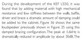
I came across a KEF document where they also mentioned the benefits of a "lossy" bracing scheme - excerpts attached.
KEF was also the company that grommet mounted the midrange in the 105 to isolate it from the box. Measured good, but didn’t sound as good as removing the grommets and properly tightening the bolts. I am always suspicios of suff that KEF “measures” into existance.
dave
- Home
- Loudspeakers
- Multi-Way
- Is MDF or plywood better for speaker cabinets?