Hi all,
I'm trying to learn to do some basic repair/up keep on my vintage gear and wanting to understand how to troubleshoot faulty parts. I've done a few recaps and have a basic understanding of things but still a greenhorn. Anyway, I have an old Mitsubishi DA-R20 receiver I'm using as my learning platform. When I got it it worked so-so. It would trip the speaker protection relays randomly and there was the usual scratchiness in some of the pots, etc. Didn't sound all that great either. I replaced the speaker protection relays and learned to set the bias and dc offset to spec which I did. I noticed some bulging caps so I did a full cap replacement. Everything seemed to be working and sounding good. Then out of the blue it went silent. Power was still on, relays went closed and I could smell heat so I turned it off and let it set. I powered it back up and took a quick measurement of the DC voltage. The right channel was still good at < 10mv. The left channel was showing 30v. Well, that's not good. I also noticed that transistor Q507 was super hot to the touch.
So I need some guidance on narrowing the issue down. I have a DMM and transistor tester and basic understanding of things but certainly understand the complexity involved so I really appreciate any assistance. I do have a service manual that someone scanned into pdf so it's a little awkward to read but it's there.
So what would be the recommendation of what to test and how? I was thinking of doing some voltage tests and reading up but need more guidance before poking around. What's the 1st thing you guys do in a situation like this?
Link to the SM. Use Chrome to view as adobe reader has an issue rendering some of the pages.
mitsubishi_da-r10-r20.pdf - Google Drive
Many thanks!
Make sure Q504 is not shorted (diode test, power off). If it's not that, I'm afraid the STK is toast. Good luck finding a decent replacement.
Q504 is a 2SB716D, a TO-92L job. Hmm. People have used 2SB647 for these, not sure whether that's the right kind of replacement. KSA992 w/ extra TO-92 heatsink maybe? (Attention, KSA may have reversed pinout.)
GSView's export function (pdfwrite @600 dpi) fixed the PDF. Not sure why it got smaller, all the pages are still there.
Attachments
Maybe some hints for you to get a basic understanding.
The power amp has 2 voltage rails, +/-50Vdc (approx) where
one rail "kind of" balances out the other giving near 0Vdc out.
Also should a component connected to a rail fail then this creates
an inbalance so no longer 0Vdc out. Typical failures are transistor
short or open collector-emitter, base-emitter... also resistors
failing open and,,, and,,,
As a first step suggest checking the +/-50Vdc power rails are ok.
Be surprised if they weren't since they come from the unregulated
supply (rectifier and filter caps only).
Next would be to check the voltages on the IC/STK. The trick is not
to probe the STK pins, one slip=toast, probe a part connected to same
node. May be a case of bs in=bs out.
Next would be diode test suspect transistors, diodes and check resistors.
...Q504... 2SB647
Indeed Q504 is suspect.
2SB716B: 120V/50mA/0.75W/400-800x/150MHz/1.8pF
2SD647: 80V/1000mA/0.9W/60-320x/--/20pF -> not really...
Ok cool. I knew there were some super smart guys here.
@Sgrossklass - thanks for fixing the pdf. Didn't even think about the dpi setting.
So Q507 is the one getting super hot. So I should check Q504 1st correct? I'm assuming the diode check across the pins needs to be done out of circuit correct yes?
@mbz - I have read about checking rail voltage but not confident I know exactly where to measure on the board. Forgive as I'm still learning. I see the +50v and -50v on the schematic but translating that to physically where to measure.
Thanks guys. I really appreciate the schooling. Trying to get this back to life to pass down to my son at Christmas.
Ok didn't see the previous post. So, Q504 I will check. Just need to know if I need to pull it 1st.
@MarsBravo - Thanks. Scratch a D647 from the list...
@MarsBravo - Thanks. Scratch a D647 from the list...
In-circuit testing should be fine here, there are a few components around the transistor that would isolate it if anything else were shorted. If it tests as a dead short (either B-C or C-E), you can remove it and confirm your measurement.
Japan transistor pinout is usually ECB, only a handful old types have BCE.
I fixed the PDF properly now (the previous one is rather fubar if anyone noticed) - had all the pages exported as images, and rotated, resorted and set DPI manually. For some reason the size almost doubled, but the PDF is no larger than all the pages in 1-bit mono PNG, so no idea what happened there.
EDIT: Hang on, I still don't quite like this...
Last edited:
The schematic is a logical connection diagram. The actual physical connections etc is shown in the board layout section of the service manual, learn how to "read" both.I have read about checking rail voltage but not confident I know exactly where to measure on the board. Forgive as I'm still learning. I see the +50v and -50v on the schematic but translating that to physically where to measure.
If you trace the +/-50V rails back you will see that they go to the main filter caps (1000uf), this should be an easy place for checking. The +ve rail will be connected to the +ve of one cap, likewise the -ve connected to the -ve of the other cap.
Finally got the PDF tamed. The PDF24 Reader "save copy" function miraculously yielded an unproblematic file, the rest was pdftk4All magic (extract / rotate / sort / join).
Now that I can read the schematic properly, I also spotted that the DA-R20 actually uses the STK1060.
Now that I can read the schematic properly, I also spotted that the DA-R20 actually uses the STK1060.
Attachments
Last edited:
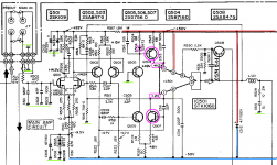
Check all components around Q504 (see diagram MitsDAR20_MainL) for shortings. If something is wrong there, Q507 heats up.
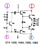
The inside of the STK1060 is added (shown in diagram STK1060).
You can check the powerrails, red is plus, blue is neg (see diagram MitsDAR20_ps).
There is a flaw in the drawing; I've added this blue line from the rectifier bridge (D21--24).
You can also check the powerrails there on the (large) capacitors C25 and C26.
I might find many replacements in my cross reference, but can you provide me a list of list of 2SBxxx transistors you can get? I'll check them which suits the B716D best.
Attachments

@sgrossklass - many thanks for fixing the svc man. Man that makes it much easier to read! Sweet!
@Mbz - Got it. Thanks for that tip. I see that now. Did about 3hrs of reading this morning. It's confusing as heck for a green horn but I'm learning a lot.
@MarsBravo - Ok, I think I hit all the stuff you said to check. Hopefully I did everything properly.
Measurements:
+50v and -50v on the big caps so looks like rail voltage is fine. I wasn't exactly sure what to do with all the green marked grounds in your attachement but to check they all had continuity to ground.
The PNP transistor Q504 measurements are:
C2B = .6v
E2B = .6
B2E = OL
B2C = OL
C2E = .4
E2C = .4
It was all looking good until collector to emitter. Shouldn't those be OL as well?
Measurements for NPN Q507
C2B = OL
E2B = 1.6
B2E = .6
B2C = .6
C2E = 1.2
E2C = .9
That guy looks all wacko. It's a 2SD756.
I checked D504 was .5 in forward bias and OL reversed. That means it's good correct?
Lastly, I checked voltage on the STK's (using mini-clips to avoid slips). The 601 was spot on for 0 and 1 (+- 1.2v) the 501 had nothing.
Ok, this is getting good. Kinda like a mystery novel. Thanks a ton for the help and patience. So, if i'm getting this, Rail voltage is fine, grounds are fine, D504 is fine but Q504 and Q507 are bad. Is that accurate? What would be next?
Thanks!
Oh, and that was all done in circuit using diode mode on my DMM except for the continuity checks of course. I do have a transistor checker on the way so I'll pull those and test them with that when it gets here.
Your on the right track. Just want to mention a couple of things. Are you using a light bulb limiter? A light bulb in series with the power cord for the amp, this limits the amount of current a short in the amp will draw ( the curent max is set by the bulb wattage ) but still lets the PS charge to full voltage if there are no faults. And its sort of an ammetter, the brighter the bulb the higher the current draw of the amp.
Also wonder why the falure happened after your mods. Are you sure your recap didnt cause the problem, and will continue to burn up stuff. A polarized electrolytic with the +/- reversed may take some time to fail. So you might want to check those before you continue.
Also wonder why the falure happened after your mods. Are you sure your recap didnt cause the problem, and will continue to burn up stuff. A polarized electrolytic with the +/- reversed may take some time to fail. So you might want to check those before you continue.
check, check+50v and -50v on the big caps so looks like rail voltage is fine
all the green marked grounds had continuity to ground
Odd, can be caused by C513, remove it and measure again.Q504: C2E = .4 ; E2C = .4
Should be OL indeed.
Also odd. It's on a differential - long tail pair with very low tail, unsure. OL is to expect too.Q507: E2B = 1.6 ; C2E = 1.2 ; E2C = .9
D504 is good... Check
...the 501 had nothing... Huh?
Q504 and Q507 are possibly bad.
Can you measure on IC501 from pin 9 to pin 6? Should be OL.
Your on the right track. Just want to mention a couple of things. Are you using a light bulb limiter?
No. I will read up on that and construct one if necessary. Thank you!
A polarized electrolytic with the +/- reversed may take some time to fail. So you might want to check those before you continue.
I thought of that as well and double checked them all. I could not find any out of polarity but I will check again just to make sure. Could have missed one. I did in some instances use a higher voltage rated cap than before (10v and 16v to 25v for example) and used Wilma 50v film caps in place of the aluminum caps at 4.7uf and smaller on advice from another. I had used it for quite a few days before it went silent.
I'll mention it but not sure it wasn't just a freaky coincidence...while I had it playing some music, I scooted across the carpet to adjust a dial and had nice static shock jump from my finger to unit. It just so happened to go silent at that moment.
@MarsBravo - Should I call you Detective MarsBravo lol?
Can do. To be clear though, remove 504 and measure it out of circuit correct?
Oh, and I think I found a replacement for 2SD756. An SK3931?
IC501 reads .007 from 9 to 6 on diode test. IC601 shows OL.
Odd, can be caused by C513, remove it and measure again.
Should be OL indeed.
Can do. To be clear though, remove 504 and measure it out of circuit correct?
Oh, and I think I found a replacement for 2SD756. An SK3931?
Can you measure on IC501 from pin 9 to pin 6? Should be OL.
IC501 reads .007 from 9 to 6 on diode test. IC601 shows OL.
Ok, whilst checking all my caps for proper polarity and just chekcing joints and all, I made a nasty discovery. Looks like I forgot to solder the phono stage daughter card back to the main board. Certainly worked when powered up but that connection had to be iffy at best. I fixed that tonight. I wonder if that, combined with my little static bolt conspired to do me in....
IMG_1658.jpg - Google Drive
Here's the whole thing from above if interested...
IMG_1626.jpg - Google Drive
Thanks!
IMG_1658.jpg - Google Drive
Here's the whole thing from above if interested...
IMG_1626.jpg - Google Drive
Thanks!
Last edited:
Been busy today lol. The transistor tester arrived today so I pulled Q507 and 504 and tested them. Looks like 504 is ok. Reading here:
Q504_good.jpg - Google Drive
Q507 doesn't look so good...
Q507_bad.jpg - Google Drive
So trying to determine what else along with 507 could be suspect. With my rookie eyes, there seems to be a lot of components along that path...
Q504_good.jpg - Google Drive
Q507 doesn't look so good...
Q507_bad.jpg - Google Drive
So trying to determine what else along with 507 could be suspect. With my rookie eyes, there seems to be a lot of components along that path...
No, just measure ohm over C513. If it has failed (shorted), you get the same problems. But......remove 504 and measure it out of circuit correct?
My library is founded in the eighties... and not up to date. If you supply a datasheet (PM), I can cross check. But......a replacement for 2SD756. SK3931?
Owww... That's no good. It's a CB from a driver bjt. Should read OL and (some) 0.7. Pretty sure (99.999%) the STK1060 has died, given the symptoms.IC501 reads .007 from 9 to 6 on diode test. IC601 shows OL.
Aside:
Mars is equivalent to my given name, the god of war (or the candy bar), Bravo after this hilarious cartoon figure just two decades ago. I do not resemble either and at all. Cloudgrin on the left is shot while leaping over Wedge WA. That was an expedition to uncover a tragic clue from a distant past. Grave but solved. MP dW
I scooted across the carpet to adjust a dial and had nice static shock jump from my finger to unit.
It just so happened to go silent at that moment.
That was no coincidence.
- Home
- Amplifiers
- Solid State
- Taking voltage measurements for troubleshooting