Hello
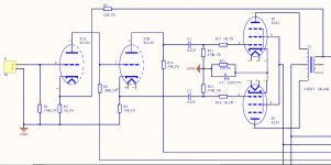
I recently built my first push-pull amplifier from a kit (ECC85+EL84).
During testing I noticed the following:
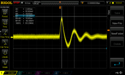
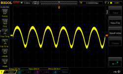
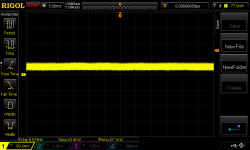
In addition to an inaudible 100Hz hum (living in Europe) there are oscillations in the same interval (see attachments). Does anyone have an idea where they could come from?
Missing grid stopper resistors?
I'm grateful for any idea.
Best regards
Parilex
P.S. Sorry for my poor English.
I recently built my first push-pull amplifier from a kit (ECC85+EL84).
During testing I noticed the following:
In addition to an inaudible 100Hz hum (living in Europe) there are oscillations in the same interval (see attachments). Does anyone have an idea where they could come from?
Missing grid stopper resistors?
I'm grateful for any idea.
Best regards
Parilex
P.S. Sorry for my poor English.
Attachments
Last edited:
Check power supply decoupling (last electrolytic in the filtration chain, and make a test omitting the resistor from the trafo's output (Open loop). Let us know if this stops the oscillation. If yes, do a re-try rewiring such resistor, but inverting both EL84's plates, possibly positive feedback.
I wonder if your power supply regulator is oscillating?
What does the screen to ground signal look like?
Be sure to use at least a 10X probe.
What does the screen to ground signal look like?
Be sure to use at least a 10X probe.
Last edited:
Good evening
Did some troubleshooting today. So far no luck.
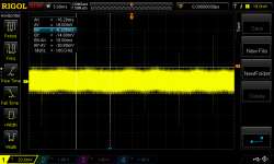
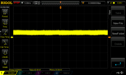
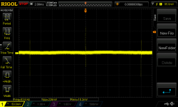
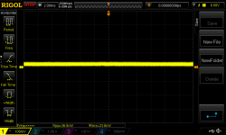
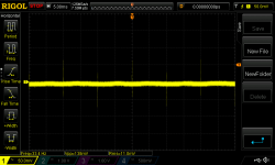
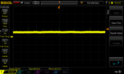
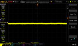
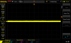
The power supply seems fine to me. Could not see that kind of oscillations there. See the attached measurements/screenshots for the +300V rail (screen) and B+.
I also added grid stoppers (1K Ohm) without seeing a change.
The oscillations are the same in both channels. In the first seconds after switching on, the amplitude slowly increases. Having disconnected all the input signals makes no difference.
The oscillations seem to appear after the first triode.
I am rather at a loss.
Did some troubleshooting today. So far no luck.
The power supply seems fine to me. Could not see that kind of oscillations there. See the attached measurements/screenshots for the +300V rail (screen) and B+.
I also added grid stoppers (1K Ohm) without seeing a change.
The oscillations are the same in both channels. In the first seconds after switching on, the amplitude slowly increases. Having disconnected all the input signals makes no difference.
The oscillations seem to appear after the first triode.
I am rather at a loss.
Attachments
-
 Point_7_AC.png39.9 KB · Views: 100
 -
 Point_6_AC.png35.4 KB · Views: 65
 -
 Point_5_AC.png34.6 KB · Views: 73
 -
 Point_4_AC.png34.8 KB · Views: 67
 -
 Point_3_AC_2.png37.6 KB · Views: 68
 -
 Point_2_AC.png32.6 KB · Views: 72
 -
 Point_1_AC.png33.4 KB · Views: 116
 -
 PushPull-EL84_Measurements.png115.6 KB · Views: 184
Good evening
Did some troubleshooting today. So far no luck.
The power supply seems fine to me. Could not see that kind of oscillations there. See the attached measurements/screenshots for the +300V rail (screen) and B+.
I also added grid stoppers (1K Ohm) without seeing a change.
The oscillations are the same in both channels. In the first seconds after switching on, the amplitude slowly increases. Having disconnected all the input signals makes no difference.
The oscillations seem to appear after the first triode.
I am rather at a loss.
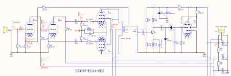
There is a question concerning a part of the schematic that is incomplete as drawn. The secondary of the output transformer is shown as only having one side connected to anything. Obviously (presumably!) you actually have a speaker connected. But what about the grounding of the other end of the secondary? Again, since this is not shown, one can only speculate on whether it has been grounded or not. But the feedback would not work properly, and could maybe have weird consequences, if the other end of the secondary were not grounded.
Thank you very much for your hints!
The output transformers are 8/4ohm ones with the 3th tap grounded to the single star ground point.
Did not change the oscillations. Still seeing them in measurement point 3 and output.Disconnect the Fb resistors from the cathode of Ecc85
Ground the input
And check
Walter
After removing both ECC85s still the same in measurement point 3, 5 and output.Also try output stage only, removing ECC85 from the socket.
There is a question concerning a part of the schematic that is incomplete as drawn. The secondary of the output transformer is shown as only having one side connected to anything. Obviously (presumably!) you actually have a speaker connected. But what about the grounding of the other end of the secondary? Again, since this is not shown, one can only speculate on whether it has been grounded or not. But the feedback would not work properly, and could maybe have weird consequences, if the other end of the secondary were not grounded.
The output transformers are 8/4ohm ones with the 3th tap grounded to the single star ground point.
Attachments

OK, try this (a bit of a long shot):
This is for certain Power Mains setups only.
(3 wire, with ground)
Plug in the amplifier, and be sure the amp Chassis is grounded to the Mains Power Ground (I hope you have the chassis grounded to the Mains Power Ground). I hope your amplifier has an IEC socket, 3 wire plug and cord, and 3 wire Mains Power outlet.
Keep the amplifier turned Off.
Plug the scope into the same Mains Power outlet (dual outlet), or closest outlet that the amplifier is plugged into. Make sure the scope ground is grounded to the Mains Power ground (I hope your scope uses a 3 wire IEC socket, 3wire plug and cord, and 3 wire Mains Power outlet).
Connect Both the probe Tip, and probe Ground clip to the amplifier chassis (the amp is off).
Any noise or pulses you see are from the Scope Switching Power Supply EMI that is emanated from the scope power cord.
Those EMI currents flow in and out of the power cord; and they returned through the probe Ground clip.
EMI (Electro Magnetic Interference)
EMC (Electro Magnetic Compatibility)
If a device passes EMI specifications, it does not necessarily mean it is "Compatible".
This is one of the tradeoffs of switcher power supplies, versus old inefficient linear analog power supplies.
I have experienced this kind of problem, at different locations, different equipment, different setups.
If you look far enough under the rug, it is there.
Last edited:
The power supply is way over-built, when a much simpler traditional (CLC/CRC) supply would be just fine.
Also, the 0.22uf output coupling caps are not needed, a 0.047uf cap in its place would be just fine.
Why does anybody get so complex with things that worked great with simple systems?
Also, the 0.22uf output coupling caps are not needed, a 0.047uf cap in its place would be just fine.
Why does anybody get so complex with things that worked great with simple systems?
wiseoldtech,
Agreed!
But if someone REALLY insists to have a regulated screen supply, there are lots of Gas Regulator tubes out there.
Requires a Gas Regulator tube and a Resistor. Simple.
(Do not put a capacitor across it, or it might become a relaxation oscillator).
They come in 75V, 90V, 105V, and 150V versions. If you need a different voltage, just
add them in series.
These have really pretty glows. And some are good looking shoulder tubes.
For those who use solid state diodes in their B+, they might not be against using Zener Diodes to regulate the screen voltage.
OK, try this (a bit of a long shot):
This is for certain Power Mains setups only.
(3 wire, with ground)
Plug in the amplifier, and be sure the amp Chassis is grounded to the Mains Power Ground (I hope you have the chassis grounded to the Mains Power Ground). I hope your amplifier has an IEC socket, 3 wire plug and cord, and 3 wire Mains Power outlet.
Keep the amplifier turned Off.
Plug the scope into the same Mains Power outlet (dual outlet), or closest outlet that the amplifier is plugged into. Make sure the scope ground is grounded to the Mains Power ground (I hope your scope uses a 3 wire IEC socket, 3wire plug and cord, and 3 wire Mains Power outlet).
Connect Both the probe Tip, and probe Ground clip to the amplifier chassis (the amp is off).
Any noise or pulses you see are from the Scope Switching Power Supply EMI that is emanated from the scope power cord.
Those EMI currents flow in and out of the power cord; and they returned through the probe Ground clip.
EMI (Electro Magnetic Interference)
EMC (Electro Magnetic Compatibility)
If a device passes EMI specifications, it does not necessarily mean it is "Compatible".
This is one of the tradeoffs of switcher power supplies, versus old inefficient linear analog power supplies.
I have experienced this kind of problem, at different locations, different equipment, different setups.
If you look far enough under the rug, it is there.
That would make perfect sense. Unfortunately, I couldn't reproduce it.
With the probe tip and ground clip connected to the amp chassis, and oscilloscope & amp both connected to same mains power ground with 3 wire cord no pulses or oscillations visible.
Parilex
Attachments
I guess that is not it.
But one more, try these settings:
Set your acquisition to peak.
Set your trigger at 18mV, like your first plots.
Speed up the time/div to 2 msec.
If that is still not it, then do the following:
Change the EL84 cathode resistor to 300 Ohms
Pull out one EL84 (the top one, that has the pulse signal from the phase splitter).
Take out the feedback resistor.
(suppose the output stage is oscillating, it could possibly feedback to the earlier stage or stages).
What about the wire dress?
You do have an 8 Ohm non-inductive resistor on the 8 Ohm output tap to secondary common, right?
Last edited:
I'm not familiar with your software 'scope, but if you are indeed showing things happening at only a few 10's of milliVolts, that's likely not oscillation. Much more likely to be switching noise from a nearby source.
Star grounding is fine on paper but often has issues with implementation. The necessarily longer "ground" wires are good antennas and unsuspected ground loops arrive with two channels' signal returns connected together somewhere else.
All good fortune,
Chris
Star grounding is fine on paper but often has issues with implementation. The necessarily longer "ground" wires are good antennas and unsuspected ground loops arrive with two channels' signal returns connected together somewhere else.
All good fortune,
Chris
There are two separate things occurring. First, something is getting “burped” at the rectified line rate, and then the amp is ringing a bit at about 60kHz in response to each burp.
My guess is, since the burp itself is short, is that it’s related to the short current surge that the power supply uses to top off the big filter cap on each half cycle. How is your grounding? Could the negative return of the cap be whispering to the input tube through the grounds?
You can separately check the ringing by looking at a square wave. Some ringing may not be bad. Compare the square wave response to other similar amps. You can further chase it by removing the feedback. If ringing is still there, then you have some other feedback path that shouldn’t be, also maybe via fishy grounds. If the ringing is gone with no feedback, then you have a feedback-induced instability.
Hi everyone
Many thanks for the hints and suggestions!
I am on duty for the next few days and therefore have little time for further testing.
Im using a Rigol DS1054Z for the measurements with 8 Ohm/50watt dummy loads connected to each output channel. I'm played around with the acquisition settings to be sure that i'm not missing the oscillations. That is why the settings are slightly different.
Disconnecting the global negativ feedback did not have any influence. I'll try with a 300 ohm EL84 cathode resistor.
The wiring is certainly not perfect, but I have tried to follow the recommendations (e.g. here Heater Wiring - the Good the Bad and the Ugly)
Since both channels are equally affected, something like this seems most plausible to me. I'm pretty sure it's not external interference, as the measurements at another location were exactly the same. The amplitude of the oscillations is indeed very small and does not influence the sound reproduction noticeably. I am simply tempted to find or explain the cause of such problems/phenomena.
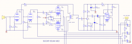
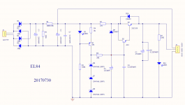
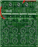
As I mentioned, it is a reasonably priced kit, but I have a good overall impression of it. Besides transformers it included two PCB boards for the power supply and the actual amplifier circuit. There are 5 points connected to the star ground point (AC input socket, power transformer, filaments center, output transformers and power ciruit board) with quite short connections. I didn't take a picture of the PCBs, but could find one from a previous board revision online. Apart from a few minor changes, they are practically identical.
Meanwhile i suspect that the oscillations come from the power supply, even though I couldn't detect them on the +350V or +300V line.
Could this possibly be a ringing from the bridge rectifier diodes as a result of the switching? (see http://peufeu.free.fr/audio/articles/Snubber Networks in Power Supplies.pdf). I'm thinking about ordering the components for a snubber network for a try. Which capacitors and resistors would you recommend for this purpose?
Greetings from the snowy Swiss mountains
Parilex
Many thanks for the hints and suggestions!
I am on duty for the next few days and therefore have little time for further testing.
I guess that is not it.
But one more, try these settings:
Set your acquisition to peak.
Set your trigger at 18mV, like your first plots.
Speed up the time/div to 2 msec.
If that is still not it, then do the following:
Change the EL84 cathode resistor to 300 Ohms
Pull out one EL84 (the top one, that has the pulse signal from the phase splitter).
Take out the feedback resistor.
(suppose the output stage is oscillating, it could possibly feedback to the earlier stage or stages).
What about the wire dress?
You do have an 8 Ohm non-inductive resistor on the 8 Ohm output tap to secondary common, right?
Im using a Rigol DS1054Z for the measurements with 8 Ohm/50watt dummy loads connected to each output channel. I'm played around with the acquisition settings to be sure that i'm not missing the oscillations. That is why the settings are slightly different.
Disconnecting the global negativ feedback did not have any influence. I'll try with a 300 ohm EL84 cathode resistor.
The wiring is certainly not perfect, but I have tried to follow the recommendations (e.g. here Heater Wiring - the Good the Bad and the Ugly)
There are two separate things occurring. First, something is getting “burped” at the rectified line rate, and then the amp is ringing a bit at about 60kHz in response to each burp.
My guess is, since the burp itself is short, is that it’s related to the short current surge that the power supply uses to top off the big filter cap on each half cycle. How is your grounding? Could the negative return of the cap be whispering to the input tube through the grounds?
You can separately check the ringing by looking at a square wave. Some ringing may not be bad. Compare the square wave response to other similar amps. You can further chase it by removing the feedback. If ringing is still there, then you have some other feedback path that shouldn’t be, also maybe via fishy grounds. If the ringing is gone with no feedback, then you have a feedback-induced instability.
I'm not familiar with your software 'scope, but if you are indeed showing things happening at only a few 10's of milliVolts, that's likely not oscillation. Much more likely to be switching noise from a nearby source.
Star grounding is fine on paper but often has issues with implementation. The necessarily longer "ground" wires are good antennas and unsuspected ground loops arrive with two channels' signal returns connected together somewhere else.
All good fortune,
Chris
Since both channels are equally affected, something like this seems most plausible to me. I'm pretty sure it's not external interference, as the measurements at another location were exactly the same. The amplitude of the oscillations is indeed very small and does not influence the sound reproduction noticeably. I am simply tempted to find or explain the cause of such problems/phenomena.
As I mentioned, it is a reasonably priced kit, but I have a good overall impression of it. Besides transformers it included two PCB boards for the power supply and the actual amplifier circuit. There are 5 points connected to the star ground point (AC input socket, power transformer, filaments center, output transformers and power ciruit board) with quite short connections. I didn't take a picture of the PCBs, but could find one from a previous board revision online. Apart from a few minor changes, they are practically identical.
Meanwhile i suspect that the oscillations come from the power supply, even though I couldn't detect them on the +350V or +300V line.
Could this possibly be a ringing from the bridge rectifier diodes as a result of the switching? (see http://peufeu.free.fr/audio/articles/Snubber Networks in Power Supplies.pdf). I'm thinking about ordering the components for a snubber network for a try. Which capacitors and resistors would you recommend for this purpose?
Greetings from the snowy Swiss mountains
Parilex
Attachments
Go back to basics.
Does the 100HZ hum reduce when the W1 is turned down or has it any effect?
If it doesn't the hum is in the output stage, if it doesn't, it is in the driver stage.
Does the 100HZ hum reduce when the W1 is turned down or has it any effect?
If it doesn't the hum is in the output stage, if it doesn't, it is in the driver stage.
Last edited:
You suspect your circuit is picking up PS radiation? A simple test is to seperate them by 30cm. Snubbers are useful when the HT shows a HF ripple at the output.Meanwhile i suspect that the oscillations come from the power supply, even though I couldn't detect them on the +350V or +300V line.
- Home
- Amplifiers
- Tubes / Valves
- Hum / oscillactions in EL84 push-pull amp