Google has not been helpful in my search for an answer to this question:
How much imbalance, in terms of DC resistance, is acceptable on the primary of an output transformer? This is your basic center-tapped primary.
The amp currently on my bench released the magic genie in a cloud of smoke via the first dropping resistor on the power rail (a 22 ohm, 2W, carbon resistor). While checking for possible suspects, I measured the OPT primary and got 69 ohms and 80 ohms respectively on the two halves of the primary. Seems like a high percentage imbalance to me and I'd like some assurance that there is not a partial short before I fire this up again.
That's pretty much normal for a budget built guitar amp OPT.
I have a bunch of 6600 ohm 80 VA Schumaker OPT's. They are all a little different, but one half is within a few ohms of 50 , and the other half is close to 60 ohms.
The number of turns in each half is the same, but one half is wound first, then the secondary is wound, then the other half primary is wound on top of everything else. The second half has a longer wind length because of the larger diameter, but it is wound with thicker wire, so it actually has the lowest resistance.
DC resistance has little bearing on AC resistance or impedance.
It can vary DC resistance wise up to 20% and be normal.
It can vary DC resistance wise up to 20% and be normal.
they wound one winding on top of the other. With the same number of turns the top winding will be longer than the one closer to the centre. the greater length of wire will have a greater resistance.
VERY common, and not a problem at all. The transformer does not work by resistance, it transforms impedance.
Alrighty then... so I applied approximately 5 VAC to the secondary and measured each side of the secondary to center and got 59.3 VAC on each. So, I reckon all is good.
a cloud of smoke .
🙄So, I reckon all is good.
Not saying it´s impossible but standard is winding all primary using same wire, in fact from same spool unless it runs out halfway.The second half has a longer wind length because of the larger diameter, but it is wound with thicker wire, so it actually has the lowest resistance.
I can imagine an OCD afflicted winder (hey, I´m OCD afflicted too) who might want to compensate and use **slightly** thicker wire, but in that case "just enough", he wouldn´t overcompensate the other way.
FWIW I *have* wound secondaries slightly thicker on purpose, so secondary resistive loss is same as primary.
But that´s something else.
Not saying it´s impossible but standard is winding all primary using same wire
Sometimes standard techniques go out the window when you get OPT's custom made by a company who does transformers for their own line of automotive battery chargers, and cost is the only criteria.
I purchased 200 of these in the early 1990's. Before I dropped that much cash I got a couple samples, tested them thoroughly in both guitar and HiFi amps, and took one completely apart....Yes, I unwound the outer half primary, then all three series wired secondaries (0-4-8-16 ohms), which were each a different wire size, then the inner half primary. I measured the wire diameters with a decent vernier caliper.
The bobbin was cardboard with no outer flange, and all insulation was simple paper with no varnish or wax. There are no end bells, just the naked transformer, obviously with cost as the main design and manufacturing criteria. They were made by Schumaker for ADA, but were never delivered to ADA since their warehouse had burned down, and they went out of business. They were all over the surplus market back then in two different primary impedances, 4400 and 6600 ohms. The core and winding techniques are EXACTLY the same as the transformer in my Schumaker 12 volt 6 amp car battery charger purchased in the mid 1980's. Somewhere I have all the data in a notebook, but that was two moves and 1200 miles ago.
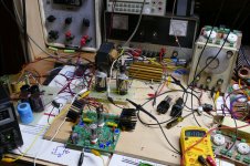
I still have a few of these transformers, and often use them for experiments that could end badly instead of risking something expensive. In almost 30 years of use, I set one on fire when a load resistor blew open at somewhere beyond 150 watts maybe 20 years ago, and severely magnetized another recently when a plate to ground arc occurred at 160 watts output on 600+ volts of B+. Coincidentally the same output tube was used for both events, a 36LW6.
The transformer can be seen in the first picture squeezing 112 watts from a pair of 6DQ6's. Its behind the tubes, and to the left of the load resistor.
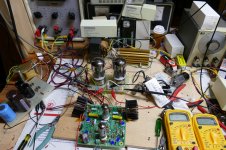
The second picture shows a pair of $$$$ NOS JAN GE 6550's in the hot seat. I get everything working with the cheap OPT's , THEN hook up the $$$$ Plitron toroids. The cheap OPT has the tube box sitting on it. The picture is not totally clear but the fat secondary wire goes to the black (0 ohm) wire, it's other end goes to the yellow wire (4 ohms), as does a thinner wire that will emerge and connect to the green wire (8 ohms), the 16 ohm wire is too thin to show easily in this picture.
The big Plitrons DO outperform the Cheap OPT's.....I paid under $20 each for the budget stuff. The Plitrons.......Used they were about 15 X more expensive.
Attachments
- Home
- Live Sound
- Instruments and Amps
- Output Transformer Primary Imbalance