It strikes me people are putting chokes in, where they don't help at all.
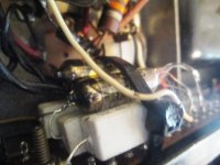
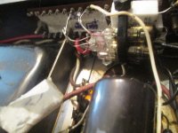
Here is a stabiliser I built up somehow, shoehorned into the guts of a MO200.
There is absolutely no room under the chassis of that thing.
It's all built up of a single tag board.
The gas stabs are wired across the main 675V HT line to give a static current of 9.5m/a, in 150V steps, giving 150v, 300v, and 450v references.
They consume less than zeners (1.4w each) are more stable, and produce less noise.
I could even squeeze an old partridge choke in there to take the hum out of the screen grid circuit.
That's the point, it's pointless doing chokes for supplies which are not ripple sensitive.
That little triode is wire ended.
A brilliant little thing that supplies ripple free 320V to the entire dual AF amp and driver stage. No matter what happens in the main current loads, it doesn't budge.
Anodes are pretty impervious to AC ripple, for the simple reason 1/ it cancel out, and 2/ the gain change of the anode circuit is insignificant compared with poor ripple rejection inherent in single ended class A drivers and poorly decoupled gain compression when HT sags.
Screen grids are very sensitive to AC ripple, which is why they often end up recycling and pumping hum and noise.
AF amps because of proper decoupling should be largely impervious to supply noise.
Just saying. Solve the real problem, not the non-problem.
Attachments

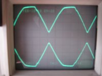
After reading your opinions AND demos i understand now well,that IN AUDIO the tuned choke with a capacitor is not a good solution.
We could have less 100 hz buzz but at the price of more hash in the 200 to 800 hz band.
Thanks to you all...
We could have less 100 hz buzz but at the price of more hash in the 200 to 800 hz band.
Thanks to you all...
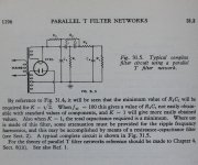
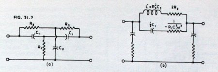
You might consider a parallel T filter network, although one might end up with impractical values...
Attachments
Last edited:
often, a T filter works best at one frequency.
An unequal balance of full wave rectification results in some fundamental 1 x line frequency coming through.
Unequal DCR in the 1/2 windings of the secondary; un-equal individual plate to filament/cathode rectifier voltage drop; and directly heated rectifiers whose filaments are not powered by a center tapped winding; are examples.
The 2 x line frequency is what many filters attack.
The 3 x line frequency can get through too, & higher harmonics, etc..
Capacitors of a given capacitance and voltage rating are smaller than ever before.
RCRCRC filters the fundamental, and more effectively filters the higher frequencies (the frequencies that we are more able to hear).
A choke makes the filter much more efficient, and rolls the mid and high frequencies at an even higher rate.
For a preamp, you may get by without a choke.
For a power amp, a choke is often needed to reduce power loss.
Last edited:
The main advantages to a resonant choke setup is that the choke can be a smaller L value, which reduces the voltage transients that occur in power supply output due to fast-changing or step loads. Power supply transients can modulate the amplifier's output and sour the sound.
Its best use is to provide better regulation for AB and B stages having large variations in current drain.
Amps like class A, and 'ultralinear' with high idling currents, etc.. do not benefit much from the resonated choke and work great with a regular LC filter.
There is some point at which a choke can work well with or without a resonating capacitor but it depends on the equipment - really more on the choke's impedance at the ripple frequency and its Q.
There is not much space to be saved by using a small low inductance choke and resonating, it because a large-ish high current capacitor is needed. Some chokes have too many henries to resonate with any effectiveness. The only built example I have:
A 30H choke on 120Hz ripple @ 2A DC load current, is not good for resonating.
A regular LC filter with that choke is very good indeed for ripple, but there is a whopping transient during pulsed signal.
A 2-5H choke resonated at 120Hz (125Hz actually) gave much better prevention of the transient and with very low ripple, there was not an issue with harmonics in this case.
The resonance should be set slightly higher than the ripple frequency because the chokes are rated inductance @ max. current, and will increase in inductance as current goes down, lowering the resonance f.
Low current draw is where resonance should be made because there is low signal and noise is more annoying in the quiet. How much to set resonance to? Just do it when the amp is idling. tune for minimum hum. carefully.
need to know:
idling current
full signal current
choke inductance at full current
choke inductance at idling or low current
choke resistance
filter capacitor value
plate transformer voltage @ zero and full load
plate transformer resistance pri and full sec.
DC output voltage expected would be nice.
Then use LTspice and simulate your power supply.
Point is that every single variable affects the 'answer' for the OP. It is not a general question. By all means try the resonating and see. Just keep in mind the many factors.
I use LTspice with a rectifier and AC source to feed the filter and see what it does with step loads and also ripple and regulation. All kinds oif things can cause surprises like the resonating cap getting hot or having too much voltage across it. Usually not problems in most home-use stuff.
Its best use is to provide better regulation for AB and B stages having large variations in current drain.
Amps like class A, and 'ultralinear' with high idling currents, etc.. do not benefit much from the resonated choke and work great with a regular LC filter.
Generally speaking do push pull stages suffer less from power supply ripple than single ended stages. Power supply rejection ratio of the circuit is the qualifier. Power supply sag is another issue, either coming from too much resistance, too small capacitor value (although other issues might arise earlier) or a mains transformer that is not up to its task. The effect of G2 voltage regulation with penthodes is dependend on the tube.
Edit: the operation of a choke is such that it opposes current changes. One should consider this property to descide where to use it.
Last edited:
often, a T filter works best at one frequency.
An unequal balance of full wave rectification results in some fundamental 1 x line frequency coming through.
Unequal DCR in the 1/2 windings of the secondary; un-equal individual plate to filament/cathode rectifier voltage drop; and directly heated rectifiers whose filaments are not powered by a center tapped winding; are examples.
The 2 x line frequency is what many filters attack.
The 3 x line frequency can get through too, & higher harmonics, etc..
Capacitors of a given capacitance and voltage rating are smaller than ever before.
RCRCRC filters the fundamental, and more effectively filters the higher frequencies (the frequencies that we are more able to hear).
A choke makes the filter much more efficient, and rolls the mid and high frequencies at an even higher rate.
For a preamp, you may get by without a choke.
For a power amp, a choke is often needed to reduce power loss.
Indeed, for best results one should inspect the ripple to see if it is symmetrical. Adding a small resistor in one leg can help. Interesting remark you made wrt the effects of a RC filter compared to a choke on mid frequencies.
No, not in this case. If you apply a voltage across a parallel LC circuit then the maximum voltage you will see is the applied voltage. In the case of a tuned choke in a typical cap input PSU we are talking about tens of volts at most.
To get high voltages you need to inject a current i.e. from a high impedance source.
Exact tuning is not needed. All you need is a significant rise in impedance at the operating frequency. You could tune the choke to 200Hz and still get a small rise in impedance at 100Hz; all frequencies below resonance see a rise in impedance.
Hmmm… so I read your reply yesterday, and thought “that's not what I learned in EE147, back when the continental ice shelves were still melting…”
Yet, it makes sense: in parallel the devices share common nodes. If one applies a voltage across those nodes, well … that's all the voltage the devices see. There can and is some shuttling of current between the capacitor and inductor; but in the end, it is the phase 'correction' of both devices at resonance that produces the notch filtering effect. Remove the choke, and you have a high-pass filter. Or, remove the capacitor, and you get a low-pass filter. Both, you have a complex plane 'zero', a notch filter.
Got it.
Unearthing the EE texts … reminds me that the Q-versus-voltage business is for L-and-C in series, not parallel. 3 nodes. If we're imagining vertically, the top-and-bottom nodes are 'driven' by a voltage-and-current AC source, say at the mathematically derived resonance of the pair. The middle node between them has the Q-dependent amplified voltage swings.
Dang, getting older than dirt is sure humbling.
Thank you again, DF96. Always a pleasure hearing from you, and noting that at least 2 or 3 people actually read what I post. All my subscripts and superscripts, italics, bolds and underlines notwithstanding. LOL!!!
GoatGuy ✓
In a parallel resonant circuit, driven by a constant voltage, it is the current shuttling back and forth between the L and C which gets multiplied by Q.
The twin-T notch can be a useful circuit, but I seem to recall reading somewhere that it has an effective Q of 0.25. This could actually be useful in a PSU application because it means that it attenuates somewhat (not a lot!) over a wide range of frequencies around the actual notch. When used for processing signals it is often bootstrapped by a slightly-less-than-unity-gain follower, which increases Q.
The twin-T notch can be a useful circuit, but I seem to recall reading somewhere that it has an effective Q of 0.25. This could actually be useful in a PSU application because it means that it attenuates somewhat (not a lot!) over a wide range of frequencies around the actual notch. When used for processing signals it is often bootstrapped by a slightly-less-than-unity-gain follower, which increases Q.
One could put a low resistance 3rd harmonic trap filter on the AC primary side of the power xfmr to give flattened sine waves for output to the rectifiers. (the input V is still 60 or 50 Hz, but the rectified currents seen at the primary contain a 3rd harmonic component) Will lower the B+ voltage output and will drop some V for any heaters too (inductor Rint). Definitely need to simulate. Should improve the rectifier performance by spreading the current out into rounded square waves.
That gives me another wild idea. Could one make an all pass L-C network do impedance transformation? (make an OT) Obviously not going to be economical unless all the L's can be put onto the same core. Sometimes big simplifications are possible.
That gives me another wild idea. Could one make an all pass L-C network do impedance transformation? (make an OT) Obviously not going to be economical unless all the L's can be put onto the same core. Sometimes big simplifications are possible.
Last edited:
smoking-amp,
I have looked at mains power at locations in several countries.
I used a scope, and a specialized differential probe (that is safe to make these measurements).
What I found was the mains power already had flat tops and flat bottoms (easy to see).
(no need to flatten it further).
And, using an FFT on the scope, you easily see the fundamental, and the very large 3rd harmonic. It stands out Far above all other harmonics, including the 2nd, and higher order harmonics.
Caution: Some have tried to connect their scope probe-tip to the Hot mains lead, and the scope probe ground-clip to the Neutral mains lead.
Do Not do this!
The voltage of the Neutral lead and Ground lead can be volts apart. They are only equal all the way back at the power mains panel on the wall.
I once measured 8V between Neutral and Ground.
You can smoke the probe's ground lead, I have seen it done!
And, do not remove the scope ground lead on the scope power plug.
Safety first.
Prevent the surviving spouse syndrome.
If you filter the 3rd harmonic from the power mains, now the power is no longer flattened, so the rectifier that drives a capacitor will have larger transients, not more gentle transients.
Want to make the rectifier's job easier? Then use a Choke input filter, instead of a Cap input filter.
Last edited:
If you filter the 3rd harmonic from the power mains, now the power is no longer flattened, so the rectifier that drives a capacitor will have larger transients, not more gentle transients.
The 3rd harmonic AC trap filter just inserts a high impedance for 3rd harmonic in series. While that would prevent 3rd harmonic from entering, the main desired effect (with rectified AC output) is to prevent drawing any 3rd harmonic current thru the rectifiers. This flattens the sine wave tops and gives smoother DC output. I have done this before, it works well (under load current). But it lowers the DC voltage output. (current peaks are eliminated) One could even put in 5th and 7th harmonic traps in series as well to get closer to a square wave (still has rounded edges), but the inductor resistance becomes a problem eventually and the V output will drop a little more besides.
Last edited:
The advantage of putting the inductor (in a harmonic trap only) on the AC side is that the magnetic core does not need to be air gapped. So will be much smaller and cheaper.
The resonator does not circulate current unless a load is drawing current, so they are not in-efficient either, but do need to be low internal resistance. You want a low loss Cap as well.
The technique is not popular due to the Vac dropping on all the xfmr rectified secondaries, including a small V loss for AC Htr windings.
Last edited:
smoking-amp,
A power supply consisting of a power transformer, a center tapped secondary, and full wave rectifier, or a secondary with a bridge rectifier, and a capacitor input filter will create lots of harmonics. The waveform will be ugly, unless the load is very low compared to the power supply's full capability. There will be Lots of harmonics.
Take a look at those large, sharp, ugly current spikes, that can be transmitted magnetically.
And without proper grounding techniques, there will also be ground loops that can cause those harmonics to be heard in the amp output. The upper harmonics are easier to hear, and/or more offensive, even if the levels are lower.
A Choke is a good way to reduce the current spikes.
Some worry about the magnetic spray from the choke. It can be dealt with.
Some worry about the expense and weight of the choke. It can be dealt with.
And more RC filter stages may be required. It can be dealt with.
I use cap input filters on some of my tube amps, and choke input filters on other of my tube amps.
You can use series trap(s), yes.
What is the magnetic spray, and what is the expense, and what is the cost of one or more traps?
Of course, whatever technique is used requires adjustment (calculation) of the power transformer's primary to secondary ratio in order to get the required amount of B+ Volts.
Large circulating currents need to have very short loops. They transmit a field.
For my B+ that uses cap input filters, the loops are:
Rectifier, Cap1, Cap1 return, Center tap. loop 1.
Cap1, resistor, Cap2, Cap2 return, Cap1 return. loop 2.
Only then, is the return of Cap2 connected by a separate wire to the amp ground. 3rd loop.
Last edited:
True, you do still want an inductor on the DC side to get rid of the higher harmonics from rectification, but it can be smaller (1/2 size) with the 2nd harmonic gone on the DC side. Probably 1/4 size L with an additional H trap added to the input as well. Diminishing returns with more traps, and complicated to design. So expense drops using a single trap, maybe for 2 traps, doubtful beyond that. Although just a small series L on the primary side could work for the -much- higher harmonics, without dropping the fundamental 50/60 Hz component noticeably.
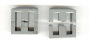
AC inductors can have far less magnetic spill than DC inductors (depending on design, no gap needed if low Mu material is used, like powdered iron toroid). And weigh and cost less too. Just more complex to design the system. A gapped AC inductor would have similar field spill as a gapped DC inductor, although gapped inductors can be made with an internal center leg -only- gap to greatly improve that. So called "distributed gap" E-I inductors, often get mentioned like they are some advanced technique, but are just a gap across the entire E-I gap, are just plain poor designs.
AC inductors can have far less magnetic spill than DC inductors (depending on design, no gap needed if low Mu material is used, like powdered iron toroid). And weigh and cost less too. Just more complex to design the system. A gapped AC inductor would have similar field spill as a gapped DC inductor, although gapped inductors can be made with an internal center leg -only- gap to greatly improve that. So called "distributed gap" E-I inductors, often get mentioned like they are some advanced technique, but are just a gap across the entire E-I gap, are just plain poor designs.
Attachments
Last edited:
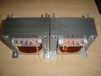
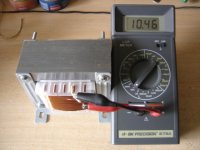
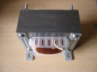
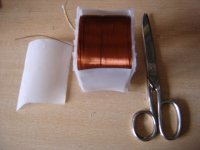
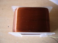
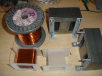
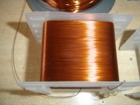
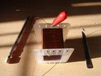
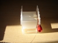
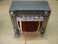
I like very much the choke input filtering method. And I able to make my own chokes. It is not difficult.
Attachments
-
 Choke 10.JPG149.6 KB · Views: 108
 -
 Choke 09.JPG144.5 KB · Views: 104
 -
 Choke 08.JPG135.3 KB · Views: 99
 -
 Choke 07.JPG159.5 KB · Views: 94
 -
 Choke 06.JPG159.9 KB · Views: 113
 -
 Choke 05.JPG144.1 KB · Views: 129
 -
 Choke 04.JPG153.6 KB · Views: 195
 -
 Choke 03.JPG145.4 KB · Views: 192
 -
 Choke 02.JPG146.4 KB · Views: 213
 -
 Choke 12.JPG124.8 KB · Views: 102

On second thought,
the AC trap inductor -WILL- have a 60 Hz current/field at -power level- while the DC inductor will have a much less bothersome DC field at -power level-. The trap capacitor does at least carry almost 1/4 the AC current, I think. The 3rd H in the trap, and the 2nd H in the DC inductor would be similar level, so comparable there.
So one would want to use a quality core design for the AC trap inductors to contain the 60 Hz field. But they are a smaller core than required for the DC inductor. (about 1/3 to 1/4 size) Best design would probably be a low Mu powdered iron toroid core, or powdered molypermalloy, or powdered nickel/iron toroid core.
Last edited:
Note that any degradation of the HT secondary winding voltage waveform may exacerbate hum ingress via heater voltage distribution and heater-cathode impedance, even with heater hum reduction techniques like tuned humdinger and elevation.
Caution is needed for choke input filtering with ss diode rectification in a HT full-wave configuration, due to snap commutation of current between diodes. Likely to need CRC half-winding snubbers, and a transient bypass cap after the diodes. Not such a concern for valve diodes as the snap is alleviated.
Caution is needed for choke input filtering with ss diode rectification in a HT full-wave configuration, due to snap commutation of current between diodes. Likely to need CRC half-winding snubbers, and a transient bypass cap after the diodes. Not such a concern for valve diodes as the snap is alleviated.
biggest issues with chokes is the resistance, it is great, but it sags the music over a few ohms.
- Home
- Amplifiers
- Tubes / Valves
- tube power supply and chokes