Just saw it using your link. Thanks. Have not yet ordered. Just wanted to make sure it was still available.
Yes, we have only one left in stock. If there is enough interest for them, we can produce some additional ones in case someone missed out on the first batch. I remember some time JP also talked about a possible new version?
Last edited:
Thanks for the info Gianluca. I'll have to make up my mind soon should I decide to pop for one. 🙂Yes, we have only one left in stock. If there is enough interest for them, we can produce some additional ones in case someone missed out on the first batch. I remember some time JP also talked about a possible new version?
@X,
On the Yarra PSU board, there are 4, 2-pin connectors pads on the secondary side where the Telmas mount. However, they are under the xformer if using the standard PCB mount Telmas. I suspect these are to be used when using an external xformer as the traces are in parallel. Correct?
Also, on the Yarra main board at locations R1041 and R1044 (10R0 resistors 2W) there are also holes for an inrush current limiter (R1042 and R1043). Are both devices to be used? It's hard to see on some of the thread images, but it appears that some users are only using the 10R0 resistor. Is there a configuration of the Yarra MB, I'm not yet familiar with that would dictate which to use?
Last edited:
Those are actually not in rush limiters but ground loop breaker between the chassis/earth ground and analog ground. Need to use one or the other 10R or NTC. But the antiparallel diodes and capacitor needs to be used.
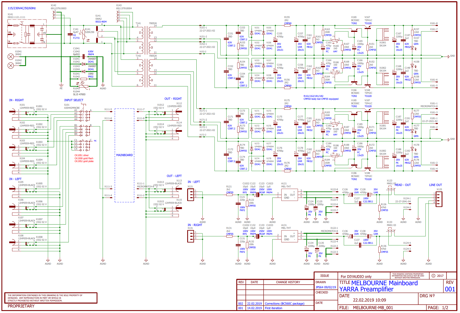
Thanks for the clarification. On one of the BOMs I had downloaded (not Vunce's), R1042/43 were labeled as SL15 47003 components. But that device IS used on the PSU as R141.
Correction: I see from the PSU schematic R141 is a S20K250 device.
Correction: I see from the PSU schematic R141 is a S20K250 device.
Last edited:
Being the noob to this thread, I had an ah ha moment tonight. I've been looking around this thread for the parts list for the Melbourne DB and simple could not find it anywhere. Vunce had provided the BOM, but that's not a parts list. Then I magically click on the Melbourne for M2X link and voila! Makes life a tad easier now.
Hopefully this may help others new to the thread as well. Those closer to the Yarra pre and Melbourne DB project, please correct the file link to a later, updated parts list if there is one.
Hopefully this may help others new to the thread as well. Those closer to the Yarra pre and Melbourne DB project, please correct the file link to a later, updated parts list if there is one.
Attachments
Good call, I forgot about the dedicated thread we had for that Melbourne.
Thanks for posting the link for the BOM of the Melbourne.
Thanks for posting the link for the BOM of the Melbourne.
From a post way back when...
Can someone give me a better idea of what JPS64 is referring to when he mentions "foil isolating the bottom panel from the main power section"?
Thanks,
Alan
Thank you @zman01.
First the bottom plate HIFI2000 Galaxy GX343 (10mm front; 2mm panels).
Then power supply part (using 5mm spacer and don´t forget to foil isolate bottom panel from the main power section).
Then preamplifier part.
Connect both together using Micro-maTch cable assembly.
Mounting potentiometer board of your choice.
Mounting side panels.
Rear panel.
IO board and connect potentiometer board using Micro-maTch cable assembly.
Mounting axis and knobs.
Finishing with top plate.
Enjoy.
JP
Can someone give me a better idea of what JPS64 is referring to when he mentions "foil isolating the bottom panel from the main power section"?
Thanks,
Alan
I think he means use nylon standoffs for the PCB so that you don’t inadvertently connect analog ground to chassis ground.
Is it OK to use 1/4 watt spec resistors at R167, R168, R187 and R188? I missed those in my order but have Vishay CMF5010K000FKEB in my collection.
Thanks
Thanks
@X , Are there any changes to the Yarra MB that are necessary depending upon what DB you are using? Kinda would defeat the general idea of a MB with 'exchangeable' modules. 🙂 I'm still working my way through the over ~900 posts to glean what I can from all the comments.
I've noticed in some of the pictures you seem to have a slightly different version of the Yarra MB and you are not using any of the big capacitors at the front of the board. I don't plan on using any boutique caps, but am building this as a general purpose pre that I can easily swap in/out the core DB modules and experiment with. At a minimum, what caps do I need to populate on the MB to use in that type if configuration.
I have fitted the PSU with the 22v Talema xfomers, as I'd like to have the extra headroom.
I'm able to follow the schematic, although it's a bit hard to read. Any chance there's a high contrast, B/W version floating around?
BTW, the boards are beautiful, albeit if it took a while to fit and solder the Melbourne DBs. Lots of parts in a small space! The PSU board came out looking very nice. Have not fired it up yet though.
I am using the 22v Telema transformers and so far have been able to use every available daughterboard with it: Melbourne, WBA18, PCA, and Korg 6P1. On the Korg, I dialed the voltage down to 29v. On the Melbourne, I had it at 30.5.
On the Melbourne, you have the option of running it DC coupled on the output. That’s why I had no caps. With the WBA18, you can go DC coupled in and out. Although I suggest caps on output as that pre had a lot of DC drift. On PCA and Korg, you have to be cap coupled in and out.
The Yarra board you have has solder mask over the vias to reduce solder bridges. Not as pretty but much easier to build.
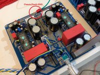
Does it help if both Yarra's PCBs sits on nylon standoff instead of the usual brass ones, to eliminate any ground loop hum or noise?
Yarra should only connect to chassis GND via top middle bolt. Use a GND strap from that bolt to chassis GND Faston tab on IEC shell.
Hi,
I have finished the PS board and the main board, but haven't done the daughter boards yet, and I have a few questions.
1) Does it make any sense to set the voltage drop at this point without the daughter boards attached?
2) I think I measure post-voltage drop at the pins on X161. At which specific component do I measure pre-voltage drop? I think an earlier post mentioned to measure after the filter capacitors, but I don't know enough about this stuff to know what point that is on the PS board, so a specific component will be helpful.
3) The back right PS board standoff appears to be a ground point. Should that be connected to, or insulated from, the chassis? Or do I need to drill the back panel so the IEC filter bolts to the chassis and makes a ground there? Or do I not need to worry about grounding to the chassis?
Thanks and sorry for all the questions.
Measure the drop from the downstream point of the large 2R2 resistors (and same as the 4700uF caps) to the output jack. I soldered some test clip pins to points on the board to get an easy hook up for the alligator clips. It is good to set the voltage drop at this point just so that the left and right channels are consistent.
The only point that should touch the chassis ground is the middle back bolt pad on the main Yarra board (this point is connected to analog 0v gnd via 10R or NTC ground loop breakers for clean GND). From that bolt, tie a ground strap using a loop crimp connector to the ground tab on the IEC shell. IEC shell can be screwed to the chassis/earth ground.
These images should help you:
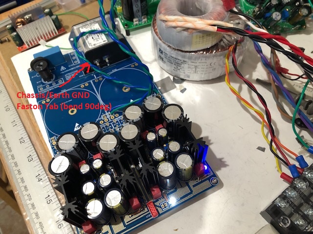
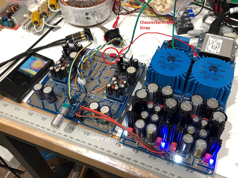
Attachments


Last edited:
Hi again,
I noticed in Vunce's shopping cart linked in post 228, the following item:
Mouser #: 584-LT4320IMSE#PBF
Mfr. #: LT4320IMSE#PBF
Manufacturer: Analog Devices Inc.
Desc.: Power Management Specialized - PMIC Ideal Diode Bridge Cntr
Is this item actually part of the build, or just something extraneous in the cart?
Is this item actually part of the build, or just something extraneous in the cart?
No, that part should not be in the cart.
I will post a clean Yarra cart tonight 🙂
- Home
- Group Buys
- The YARRA Preamplifier/HPA for Melbourne DB Group Buy