Ok. First you can test, how the opamp runs without the notch. You can use the metal film resistors divider at the input of the opamp. The signal level at the divider output must be the same as you have after the notch.I am using this mimic:
NE5532 is interesting in fact that it differs from others more "usual" OA that it doesn't like simmetrical impedances at it's inputs (in non-invert).
For others OA simmetrical impedances usually lower distortions (4562, 49860 etc).
Thats why 5532 is better as second OA (with non-simmetrical impedances) in last circuit.
For others OA simmetrical impedances usually lower distortions (4562, 49860 etc).
Thats why 5532 is better as second OA (with non-simmetrical impedances) in last circuit.
Last edited:
I am using this mimic:
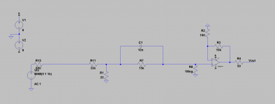
What is that input buffer? That will generate common mode distortion. Replace it with an inverting stage.
Jan
Ok. First you can test, how the opamp runs without the notch. You can use the metal film resistors divider at the input of the opamp. The signal level at the divider output must be the same as you have after the notch.
voilá!
Attachments
What is that input buffer? That will generate common mode distortion. Replace it with an inverting stage.
Jan
Tribute to the outside world: impedance converter.
Very nice!voilá!
Now you can connect the 10nF capacitor in parallel with the 15kohm resistor between the divider output and opamp input.
Does it have to be a FKP? I'll do it tomorrow, I have to go to bed now ;-)Very nice!
Now you can connect the 10nF capacitor in parallel with the 15kohm resistor between the divider output and opamp input.
I forgot to ask, what is the divider output impedance? Is it the same as your oscillator has? Good to have similar values.
Yes, for more clear results this capacitor can be the FKP2. You can connect two 22nF in series if you haven't the 10nF.Does it have to be a FKP? I'll do it tomorrow, I have to go to bed now ;-)
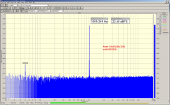
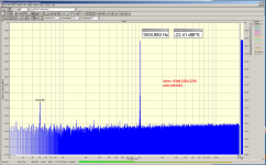
Post notch signal is relatively low.
Passive twin T notch has capacitive and low output impedance at high frequencies (when the source has also low impedance).
Here is where the problem arises- You need to figure the capacitance change vs level (say 1 pF for simple calculation) in ratio to the source impedance. If the source is 1K Ohms at 1 KHz 1 pF is 159154943 Ohms then the ratio is 159154 or -104 dB. .1 pF would be 124 dB. When you are at -160 dB it takes very little to compromise the performance. But with the 40 dB of gain it could still be significant. All semiconductor materials show a C/V modulation. You need to figure that into the design.
Did I understand you correctly?Yes, for more clear results this capacitor can be the FKP2. You can connect two 22nF in series if you haven't the 10nF.
Attachments
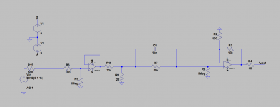
Sorry, I ignored your buffer before the notch. It may be as potential source of the distortions, as Jan noted.I am using this mimic:
So, the source output impedance is near to zero. You may leave the divider as it is, if no visible distortions. Just place the described RC at the opamp input.
If I properly understand, we are talking about the opamp after the notch? The signal level after the notch is little higher than 2mV in this case (if the 40dB amplification gets app -18dB when the 0dBFS is 2V). So, the opamp input capacitance changes must be negligible.Here is where the problem arises- You need to figure the capacitance change vs level (say 1 pF for simple calculation) in ratio to the source impedance. If the source is 1K Ohms at 1 KHz 1 pF is 159154943 Ohms then the ratio is 159154 or -104 dB. .1 pF would be 124 dB. When you are at -160 dB it takes very little to compromise the performance. But with the 40 dB of gain it could still be significant. All semiconductor materials show a C/V modulation. You need to figure that into the design.
Tribute to the outside world: impedance converter.
I understand that, I was asking for the type. Cant read it. But again, non-inverting stage generates common mode distortion right at the filter input. Why not just put in an 1x inverter and fix that??
Jan
Last edited:
voilá!
So what does this show? It shows that the distortion is better than about -105dB. Do we all understand that?
The correct number cannot be seen because it is in the noise.
Jan
How do you realize a high input impedance with an inverting OP?I understand that, I was asking for the type. Cant read it. But again, non-inverting stage generates common mode distortion right at the filter input. Why not just put in an 1x inverter and fix that??
Jan
That's the dilemma of a notch filter.So what does this show? It shows that the distortion is better than about -105dB. Do we all understand that?
The correct number cannot be seen because it is in the noise.
Jan
- Home
- Design & Build
- Equipment & Tools
- Low-distortion Audio-range Oscillator