During restoration of these old speakers, I have become aware of the service-update, regarding tweeter protection. Does anyone have information were to mount capacitor C8 and fuse F1, as described in the service manual supplement on tweeter protection. Manual on Hifi-engine.
Kind Regards from Denmark
Ps. All 68uF capacitors measure from 82-86 uF, isn't that a quite large tolerance.
Kind Regards from Denmark
Ps. All 68uF capacitors measure from 82-86 uF, isn't that a quite large tolerance.
I had a pair of 6000a that I redid.
Not sure about finding the specific area that protects tweeter but I went a lil further.
Disassembled the speaker, rotated the woofers, and removed the crossover from cabinet. I made painful efforts to retrace the original PCB and used the inductors off the old board, replacing the electrolytic caps with new ones, and bypassing them all with small 0.1uf or 0.01uf MKP caps (forget which... think 0.1uf... whether this had any benefit is unknown - not compared to stock).
What was evident though was that the refreshed crossover gave new life to these speakers, removing a hint of a veil that was somewhat noticeable and motivation for my modifications. I believe the cost was $40usd total for the parts, and very much worth it.
To this day I regret selling those speakers. They were something special.
Hi Sorensen,
assuming there is logic (there seems to be) in the parts number convention of the proposed modifications, the fuse F1 should be just before C4 (in series with it) and the C8 in parallel with R2 (6R8) because it appears to me this is the only place worth putting this part in order to slightly reduce the tweeter loading in its HP section. The C4 modification from 15uF to 10uF is already doing a good job. The 68uF caps being larger in value does not present a problem, it may be for the better in fact.
I'd appreciate if you pulled the variable resistor VR1 out and measured its values(3-2; 2-1) at a couple of positions (9, 12, 15 o'clock).
Last edited:
Hi Sorensen,
assuming there is logic (there seems to be) in the parts number convention of the proposed modifications, the fuse F1 should be just before C4 (in series with it) and the C8 in parallel with R2 (6R8) because it appears to me this is the only place worth putting this part in order to slightly reduce the tweeter loading in its HP section. The C4 modification from 15uF to 10uF is already doing a good job. The 68uF caps being larger in value does not present a problem, it may be for the better in fact.
I'd appreciate if you pulled the variable resistor VR1 out and measured its values(3-2; 2-1) at a couple of positions (9, 12, 15 o'clock).
VR1 measurement.
Speaker 1
9 12 15
2-3 14 8.4 3.3
1-2 600K 640K 510K
Speaker 2
2-3 6.6 5.1 2.1
1-2 850K 1.3M 1.6M
Now this can't be good.
Attachments
That is a weak link maybe... I heard another person mention theirs had breaks and cut out.
My variables weren't that great either. One would cut out when you'd dial the tweeter back about 1/6 way, but left both set to wide open usually, so it wasn't an issue for me at the time. I never measured them through the rotation at spots, except to ensure both were same at that max setting.
Are you modifying the crossover or is this an extra protection that is in the manual?
The principle of the VR1 seems alright, it reduces the series resistance as it gets turned to the right. The exact position for both of the speakers with equal amount of padding should probably be set by measuring spl.
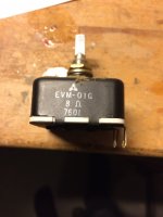
Sounds like pin 1 is not even connected, and the pot from speaker 1 could use a cleaning. 8 ohm could actually be a wirewound. Do these open without drilling out any rivets? or similar fun?
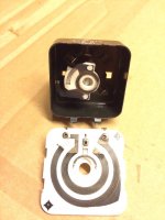
Disassembled the potentiometers, no rivets just un-bending four flaps. After some cleaning the resistance from 2-3 ranges from 7.7 to 0 on the first and 15 to 0 ohms on the on the second potentiometer. Guess I could mount a 18 ohm resistor in parallel with 2-3 on the "bad" potentiometer.
The potentiometers is quite an open construction. Foam mounted on top of the housing had dried out. Resulting in particles of foam on the resistor strips.
The potentiometers is quite an open construction. Foam mounted on top of the housing had dried out. Resulting in particles of foam on the resistor strips.
Attachments
- Home
- Loudspeakers
- Multi-Way
- Technics SB-6000 restoration