Hello all I have some valves I take out of and old record player, basicly I just disassemble it all, and gut it to parts, does anyone have some goog shecmatic what can I do with the valves and the output transformer, the valves are ucl 82 uy 85, the amp itself when working YouTube and if some one need elektor designa of El 84 el156 or kt 88 amplifier I have them and iam willing to share them
Last edited:
50volt heaters are the main draw back. In the Dansette record player, the motor had a 95volt tap on it to run the heaters, the voltage would rise to 105volts when spinning up hence slightly lower voltage, on the UCL82 and UY85. Today you will need 150volts for HT and 50 volts for heaters.
Cheaper to use different valves. Maybe E type for 6volt heaters to match available transformers.
The output transformer will match most any valve.
Cheaper to use different valves. Maybe E type for 6volt heaters to match available transformers.
The output transformer will match most any valve.
Last edited:
The original un-molested record player was THE way to use these tubes. You could have kept it all together, added a line isolation transformer, made some small mods, and had a FINE amplifier. I used to do that, just adding filtering and NFB.
I agree with you but since I wanted to use it with my computer and since I have small children I didn't want to leave open case, so I dicede to make a wooden case or better reagent a used wood box and mount it inside but since I did it, didn't work good, so iam trying to build it better by scratch, my plan is to buy a isolation transformer for the audio and one for the 220 vac, and reporpuse the old can capacitor, it's working OK I mesure with capacimetre and it's OK, now iam just chasing the shecmatic for it if you can help my I will by glad the model as piliphs ag4656
hello iam planing to reporpuse the output transformer, use an isolation transformer for audio and for the 220 v ac, reporpuse the old uy85 the old can capacitor, and the ucl 82 and trying to make it a mono amplifier, but I can find no shecmatic than can suit my the model it belong as the piliphs ag4656 , I thought in maybe ad some mods to the original design and rebuilt again50volt heaters are the main draw back. In the Dansette record player, the motor had a 95volt tap on it to run the heaters, the voltage would rise to 105volts when spinning up hence slightly lower voltage, on the UCL82 and UY85. Today you will need 150volts for HT and 50 volts for heaters.
Cheaper to use different valves. Maybe E type for 6volt heaters to match available transformers.
The output transformer will match most any valve.
I would use a transformer with 2x24 secundaries (it is cheaper than a insulation transformer). Wire the secundaries in series: the 48V AC are fine for the UCL82. A voltage triplier will get the 150V for the anodes. The UY85 tube will not be reused. You only need to buy 1x 24+24V transformer, 3x 47uF 350-400V capacitors (100uF would be best - you will find one capacitor of this kind inside any scrapped consumer electronics power supply) and 3x UF4007 diodes. There is a even cheaper option: use a 2x48V or 2x55V transformer. They are bulky and may be comparatively costly when bought new (the best RS components price today is 15 euro+VAT+shipping) but are a common surplus item. Connect the secundaries in series and use the center tap for UCL82 the filament. Use a UF4007 diode to get a 120-130V supply for the anodes. I suggest to use this diode, the modern equivalent of the UY85 tube, because single wave rectification would result in 50Hz hum that is better masked by the small speaker and transformer compared to the 100Hz hum you would have with a the today ubiquitous full wave bridge rectifier. 120V is lower than the optimal value but the circuit will still work. If you plan to buy new components, I strongly suggest to buy a replacement for C9 (100nF 630V is fine) and add a bigger filter capacitor in parallel to C2 (220uF 200V, as example). Non Hi-Fi performance with audible hum and limited frequency response are to be expected, but despite this (on my experience) those cheap record players with UCL82 had a better sound than the average modern small computer/bluetooth speaker made of plastic.
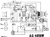
You have done the right thing by dismantling the original amplifier. It had major electrical safety flaws - the lack of the insulation transformer is only one of them. I attach the original schematic for hystoric purposes only, it should not be used to build an amplifier today. Some capacitor/resistor values are tuned to compensate the original loudspeaker lack of high frequencies and the 50Hz hum.
You have done the right thing by dismantling the original amplifier. It had major electrical safety flaws - the lack of the insulation transformer is only one of them. I attach the original schematic for hystoric purposes only, it should not be used to build an amplifier today. Some capacitor/resistor values are tuned to compensate the original loudspeaker lack of high frequencies and the 50Hz hum.
Attachments
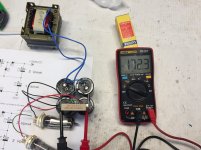
hello, thx for the repply, I wanted to use the 2 valves but if not possible I will jus let the uy 85 with filaments on just as a decorative thing, do you have any shecmatic of a reporpusal amplifier that uses this valve, I will let some photos of the parts I repursed and the valves are stored,I would use a transformer with 2x24 secundaries (it is cheaper than a insulation transformer). Wire the secundaries in series: the 48V AC are fine for the UCL82. A voltage triplier will get the 150V for the anodes. The UY85 tube will not be reused. You only need to buy 1x 24+24V transformer, 3x 47uF 350-400V capacitors (100uF would be best - you will find one capacitor of this kind inside any scrapped consumer electronics power supply) and 3x UF4007 diodes. There is a even cheaper option: use a 2x48V or 2x55V transformer. They are bulky and may be comparatively costly when bought new (the best RS components price today is 15 euro+VAT+shipping) but are a common surplus item. Connect the secundaries in series and use the center tap for UCL82 the filament. Use a UF4007 diode to get a 120-130V supply for the anodes. I suggest to use this diode, the modern equivalent of the UY85 tube, because single wave rectification would result in 50Hz hum that is better masked by the small speaker and transformer compared to the 100Hz hum you would have with a the today ubiquitous full wave bridge rectifier. 120V is lower than the optimal value but the circuit will still work. If you plan to buy new components, I strongly suggest to buy a replacement for C9 (100nF 630V is fine) and add a bigger filter capacitor in parallel to C2 (220uF 200V, as example). Non Hi-Fi performance with audible hum and limited frequency response are to be expected, but despite this (on my experience) those cheap record players with UCL82 had a better sound than the average modern small computer/bluetooth speaker made of plastic.
You have done the right thing by dismantling the original amplifier. It had major electrical safety flaws - the lack of the insulation transformer is only one of them. I attach the original schematic for hystoric purposes only, it should not be used to build an amplifier today. Some capacitor/resistor values are tuned to compensate the original loudspeaker lack of high frequencies and the 50Hz hum.


I attach a power supply schematic I have built: it does provide almost exactly the voltages and currents your need. UCL82+UY85 filament supply is DC (no hum), they need 100mA at 88V . The circuit does provide 84V : close enough and whitin the tolerances. UCL82 datasheet does specify B+ = 170V at 41+4=44mA. I measured 172V over a 3.9K resistor. So, with 4x high value capacitors , 4x 1A diodes and a 18+18V transformer it is possible to use the UCL82 while removing the hum due to the high voltage filament and keep the UY85 as decoy. For a stereo version (2x UCL82 - no UY85) a 2x 24V transformer is needed, because the filament supply should rise to 100V and the 200V B+ does provide a little more performance. To optimize costs, top two capacitors may have lower value.
Attachments

Last edited:
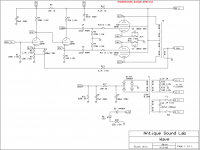
Do you have 4 UCL82 or can you get more?
See attached schematic for the ASL Wave 8. Hook all four filaments in series, get an isolation transformer with a 200 volt secondary. Run the filaments on AC from the secondary. Also rectify the secondary with SS diodes. With 4 tubes you'll have an 8 watts per channel stereo push-pull amp. The OPT should be about 10K ohms P to P.
Steve
Attachments
...I can find no shecmatic than can suit my the model it belong as the piliphs ag4656 ...
Philips AG4656 schematic is easy to find:
Philips AG 4656 - Manual - Portable Record Player - Vinyl Engine
Library Downloads - Vinyl Engine
- Home
- Amplifiers
- Tubes / Valves
- Ucl 82 uy85