That is the exact opposite to what I've heard from some mates of mine who did a lot of comparative listening between passive and active ATCs.
Those passive crossovers eat a lot of detail. That can be euphonic but it is not accurate or HiFi.
+1. Actually, a number of obvious reasons why audio systems sound better when the amps are connected directly to the drivers.
B.
As this thread already seems hijacked:
I built new 3way speakers this summer and used a dbx Venu 360 DSP with 6 LM1875 amps and a laptop connected via USB to an RME DA/AD converter to feed a AES/EBU signal into the dbx. It was very useful to figure out crossover points and slopes.
From what I got from playing with the DSP I built passive speaker level crossovers (1st order series). What bugged me most from the beginning was that the tweeters never seemed to really integrate. Having switched to the speaker level passives (signal still from the laptop to the RME into the dbx, set to 20 to 20k allpass into a pair of LM1875) the tweeters suddenly did integrate and there was a lot more detail to be heard.
Does anybody here (Ben?) have an idea what to look into what I did wrong with the DSP?
...Does anybody here (Ben?) have an idea what to look into what I did wrong with the DSP?
Ah, very good question. First of all, you did exactly the right thing. Nuts to try to guess what's the crossover that will sound right in your room when you can simply mock it up very fast with an adjustable electronic XO like the Behringer CX or DCX.
Here's where there's "a slip between the cup and the lip", actually a few places. First of all, I'd use a mic to first get about where you want to go for the XO in terms of XO point and slopes. You may find mix-and-match slopes and, no kidding, also XO points. Then fine-tune by ear. Not a simple matter to use a mic, not at all. FR changes with each few inches of movement of the mic location.
Then I'd measure what is actually getting to the drivers. Then I'd try to have the same signals using a passive unit (but I sure would like to have adjustments always available ever after anyway).
You can't make a passive crossover from "first principles" or just using the fantasy T/S values supplied by the manufacturer or crudely measured by yourself. Inaccurate and the the driver impedances vary and the room changes things, etc. But as a first try, you can try to duplicate the electronic XO signals your found in the first steps by verifying that is what is really getting to the drivers using your passive XO and not what you believed using a sim.
Any of that apply to how you worked?
B.
Last edited:
It's a 3 way horn speaker, so T/S parameters are somewhat useless. 2 of the 3 drivers don't have any documentation and my measured parameters for the third where (for that specific case) better than the datasheet.
I did my impedance plots to get an idea how to not destroy the drivers, put autoformers on the mid and tweeter with a shunt rheostat to dial in my impedances. Did FR and phase plots to get an idea what useful ranges are to cross.
Listened to the woofer full range to get an idea what it does. Added the midhorn with only a high pass and listened to that as a two way, playing with crossover points and then adding the tweeter. Checking and correcting time alignment along the way.
I did FR plots in various positions, in my case they didn't change drastically from one spot to another. "drastically" is a fuzzy term here, let's say I'm not in the +/- 1dB flat camp when it comes to speakers.
When I felt what I got from the DSP was as good as it might (apart from that damned tweeter never really integrating but always somehow being a little seperate) get I simulated and built the passive XO, curious if perception would change.
That's about how I usually do it.
Does anybody here (Ben?) have an idea what to look into what I did wrong with the DSP?
What slopes did you use with the DSP?
A textbook 1st order filter from DSP is usually not equal to a 1st order passive filter.
With the capacitor winding direction crossing the inductor. Would I be right in thinking these capacitors are made with a non-inductive wind, so minimal sensitivity to stray fields anyway? Then there's shielding if you measure anything unwanted.I thought about stacking - maybe put the 0.82mH on its back with the 15μF on top; the 10μF next to that with the 1.5mH on its end next to that with the 12Ω on top of the 10μF.
Don't worry, we have that sorted 😉A textbook 1st order filter from DSP is usually not equal to a 1st order passive filter.
How do you put it into words?when made passive with high-end amps.
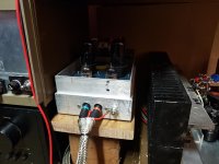
Edit:, can you see the recycled ClarityCap bypassing the 6V6s.
Attachments
Last edited:
Don't worry, we have that sorted 😉
I'm not worried, I just said that.
But who is "we"?
Ah, but they are silver and are bound to make a huge difference to the sound Zuhl! 😉
!
But they don't have go faster stripes !
The electrons will be slowed down.
@YSDR,
Just a tongue in cheek response. You're right to point out the potential discrepancies. They're due to incorrect design, not the filter.
Just a tongue in cheek response. You're right to point out the potential discrepancies. They're due to incorrect design, not the filter.
Last edited:
My 2c worth, schiirm did you check the actual acoustic slopes of the drivers, and relative phase between the drivers for both the Active and the passive setup?
My guess is that you lucked out and the passive gave you a better slope and phase match than the active did and that's why the speakers seemed to integrate better.
Note that this is something you can only check with quasi-anechoic (eg gated) measurements. Non gated in room measurements will be useless for trying to compare.
edit: it would also be interesting to see the final (combined) quasi anechoic response using both types of crossovers.
edit2: the best comparison would be horizontal polars every 10 deg through 180 deg for both crossover implementations.
Tony.
Last edited:
Are the new caps replacing C1 and C4 in your diagram?
I was of the belief parallel caps made little difference (unless you need specific values with lower tolerances - such as series notch filters sans resistor for primary cone breakup at a very specific frequency for example).
I've been using Bennic's NP electrolytics in my 3 ways for all the parallel larger value (> 8uF) caps. Using Clarity SA I think? (purple jobs) in series for the tweeter and a Solen PP for the series 80uF midrange cap (that's a huge sucka).
I'm very happy with the sound. I've got a Pi HAT HDMI 7.1 DAC to try for an active setup in due course.
My 2c worth, schiirm did you check the actual acoustic slopes of the drivers, and relative phase between the drivers for both the Active and the passive setup?
My guess is that you lucked out and the passive gave you a better slope and phase match than the active did and that's why the speakers seemed to integrate better.
Note that this is something you can only check with quasi-anechoic (eg gated) measurements. Non gated in room measurements will be useless for trying to compare.
edit: it would also be interesting to see the final (combined) quasi anechoic response using both types of crossovers.
edit2: the best comparison would be horizontal polars every 10 deg through 180 deg for both crossover implementations.
Tony.
Hi Tony (and everyone else giving my some input). I time aligned the drivers, assuming that also phase aligns them but I will look into phase again and see what comes up.
@YSDR,
Just a tongue in cheek response. You're right to point out the potential discrepancies. They're due to incorrect design, not the filter.
It regularily comes up, that a 6dB electric filter doesn't necessarily give a 6dB acoustic rolloff. How relevant is that in a non-academic sense?
It indicates techniques/methods. The untrained can learn habits that will lead to poor understanding/stagnating progress and poor results. I'd like a dollar for everything I've had to un-learn about audio.How relevant is that in a non-academic sense?
In this case, it is not a 6dB filter if the load changes, ie the load is taken into account in the design. Been that way for more than 100 years.
Last edited:
It regularily comes up, that a 6dB electric filter doesn't necessarily give a 6dB acoustic rolloff. How relevant is that in a non-academic sense?
The writer did not know where was the problem with the DSP crossover vs. the passive one, might be that or might be other thing, but this is one possibility.
- Home
- Loudspeakers
- Multi-Way
- OMG! They're huge!