Hi people,
I not long ago built a 15w el84 guitar amp which for the most part works. my problem seems to be an oscillation in the effect loop recovery stage. the output to the speaker is 20vpp @15kHz.
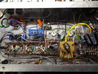
with the effect loop taken out (volume pot going straight into the PI) there's no oscillation. with a mono jack plugged into the fx loop (recovery stage muted) there's no oscillation. with the mosfet stage bypassed (volume pot -> attenuator -> recovery stage) oscillation comes back. il send a picture of the layout, if anyone can spot some glaring issue i've over looked and schematic of the output stages are attached.
if anyone could help it would be much appreciated
I not long ago built a 15w el84 guitar amp which for the most part works. my problem seems to be an oscillation in the effect loop recovery stage. the output to the speaker is 20vpp @15kHz.
with the effect loop taken out (volume pot going straight into the PI) there's no oscillation. with a mono jack plugged into the fx loop (recovery stage muted) there's no oscillation. with the mosfet stage bypassed (volume pot -> attenuator -> recovery stage) oscillation comes back. il send a picture of the layout, if anyone can spot some glaring issue i've over looked and schematic of the output stages are attached.
if anyone could help it would be much appreciated
Attachments
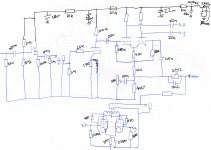
I notice there is neither a "gate stopper", nor a build-out resistor, in the MOSFET buffer stage. MOSFETs have much higher transconductance than valves, so they're even more likely to oscillate....with the mosfet stage bypassed (volume pot -> attenuator -> recovery stage) oscillation comes back.
I suggest inserting, say, a 10k gate stopper (between MOSFET gate and the junction of the two 2.2M resistors), and a 1k - 4.7k build-out resistor between MOSFET source and the 100nF cap.
This may or may not turn out to be the source of the problem you describe, but IMO it should be done anyway.
If it's not the MOSFET, my first suspicion is the gain recovery stage, whose AC operating conditons are affected when you bypass the MOSFET; that changes the impedance it sees at it's grid. It's hard to see why it would oscillate, though, being a quite generic common-cathode inverting gain stage.
I also note that there are no grid stoppers in the LTP phase splitter. I suggest adding them, say 10k - 47k in series with each grid. An LTP circuit has one output that's in phase with its input, and even a little stray coupling between those two can cause oscillation. Leonidas Fender probably left these out to save a couple of pennies with each amp he built, but it makes no engineering sense to leave them out.
-Gnobuddy
Thanks for your reply.
I added a gate stopper and build out resistor along with 2 grid stoppers between the 680k resistors and grids. It gave me a lot of hum with no oscillation and when I got rid of the hum the oscillation is still there. Shorting the 33k resistor before the mosfet caused a lot of hum, and plugging a mono jack into the effect loop intermittently causes hum when it's inserted/removed. I've checked my wiring and can see no cause for this.
Ricky
Adding a gate stopper and build-out resistor should not cause hum. Something else is wrong. (And you really should put the gate-stopper, grid-stoppers, and build-out resistor back; they are needed.)I added a gate stopper and build out resistor along with 2 grid stoppers between the 680k resistors and grids. It gave me a lot of hum
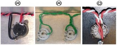
I notice your heater wires aren't twisted for a good inch or two near each tube socket. That big open loop of untwisted heater wire will inject lots of hum into nearby components. The attached image shows how to do it (and how not to do it.) Your heater wiring looks like the middle image, which is one of the ways not to do it.
There is a sticky thread on heater wiring that might also be useful: Heater Wiring - the Good the Bad and the Ugly
Shorting this resistor should make the amp dead quiet. The fact that you hear lots of hum instead is another clue that there are other things wrong; likely either bad grounding layout, or bad heater wiring. It could also be the entire amp is oscillating (at too high a frequency to hear), and the hum you're hearing is an artifact of that.Shorting the 33k resistor before the mosfet caused a lot of hum
The word "intermittently" is another clue. I suspect your amp may be oscillating continuously, and bursting into hum at those moments when the oscillation is interrupted (such as by inserting a plug into the effect loop.)...plugging a mono jack into the effect loop intermittently causes hum when it's inserted/removed.
What sort of diagnostic / test equipment do you have? Problems like this are really difficult to track down without an oscilloscope, as there is no way to see what's actually going on.
-Gnobuddy
Attachments
Thanks for the heater tip.
I never took those resistors out. I have a scope. I've probed the entire amp and the oscillation is only in the final stages of the amp. The hum being intermittent leads me to believe it isn't the heaters but that could explain some background hum.
I never took those resistors out. I have a scope. I've probed the entire amp and the oscillation is only in the final stages of the amp. The hum being intermittent leads me to believe it isn't the heaters but that could explain some background hum.
That's good news! 🙂I have a scope.
You're dealing with (at least) two separate problems: hum, and oscillation....hum...oscillation is only in the final stages of the amp.
Oscillation will mask just about every other problem, so it needs to be tackled and cured first. Once the amp is stable, you can then start to address the hum issues.
Okay, then. Let's focus on the oscillation issue.
Is it really only the final stages (output stage?) that oscillates? Try disconnecting the output valves from the phase splitter. Do you still see oscillation on the output valve anodes? (Remember that there's enough DC and AC voltage here to fry your oscilloscope. You'll probably need 100:1 'scope probes rated for a few kilovolts to keep everything safe.)
If the output valves by themselves are oscillating, find and fix the problem. Are the screen grid stoppers mounted right on the valve socket? Are the wires from the anode at a sufficient distance from the control grids? Are there control grid stoppers (your schematic doesn't show any)?
Incidentally, using much bigger than usual grid stoppers on the output valves makes the amp overdrive better, with less blubbering and sputtering and "choking out" (blocking distortion.) Instead of the timid 1k or 1.5k often seen, start with at least ten times that much: 10k - 15k is a reasonable minimum, and 100k - 150k is usually fine (but watch out for the total resistance from grid to ground, which shouldn't exceed the datasheet spec.)
Pentodes have very little Miller effect or input capacitance, so you can use some really big resistors here without affecting the amp's treble response.
Once you're sure the output stage isn't oscillating by itself, it's time to re-connect the phase splitter, and repeat the process. If oscillation re-commences, you now have to debug the phase splitter stage.
Incidentally: the final stages of the amp are where you have the largest AC voltage swings of all. Peak-to-peak signal swing at the output valve anodes can approach twice B+ voltage, so you might very well have 700 - 800 volts peak-to-peak there. Typically this enormous signal will run through several inches of wire to the output transformer primary winding.
Meantime, the input of a typical guitar amplifier will be sensitive enough to drive the amp to full output power with just a few millivolts of input; classic Fender amps often specify 20 mV input signal for full output, and those are low-gain, clean tone only, amps.
So imagine what happens if stray coupling or poor layout or poor grounding allows even a tiny, tiny, fraction of the 700-odd volts at the OT primary to leak back to the input? Your amp becomes an oscillator.
My calculator says that 20 mV is only one part in 35,000 of 700 V. It doesn't take much stray capacitance to cause that tiny amount of output signal to bleed back to the input.
In your photo, I see grey shielded cable (coax cable) running around a bright-blue bit of perfboard, and then terminated within an inch or so of one of the 9-pin valve sockets. Is that coax cable carrying a low-level signal from somewhere near the input of the amp? Is that 9-pin valve carrying a much higher signal level (I'm guessing it's an output valve)? If so, that wire shouldn't be routed anywhere near that close to the valve.
That same coax is also routed within what appears to be a quarter of an inch of some heater wiring. If the coax is carrying a low-level guitar signal, this could cause unnecessary hum.
-Gnobuddy
It is sometimes tricky to do a hum free layout. I learned my lesson on my first tube amp. The power transformer was too close to output transformer and I was getting hum through the magnetic coupling. I had to move the output transformer further away from power transf. and add some shielding between those two. Then the hum completely disappeared. 🙂
I briefly owned a Fender Blues Junior, and it had the same problem. It was a rather weird experience to pull the output tubes, and still hear hum in the speaker!...The power transformer was too close to output transformer and I was getting hum through the magnetic coupling...
-Gnobuddy
Well I pulled the power valves and the oscillation went away. I have a suspicion there's interaction between the wires on the way to the transformer and the mosfet input. However when I turned it on after changing the Penrose grid resistors from 1.5k to 10k (Sorry forgot to draw them) I had a smaller oscillation with guitar signal coming through, 5 seconds later all sound cut and was replaced with loud hum. I think I'm going to get a new chassis and rebuild this amp. With improved layout. Quick question. Can an output transformer be next to a power transformer at 90 degrees? Or should there still be space?
Orientation might help to some degree but distance is more important. Keep them as far apart as possible. I still get some coupling without shielding. The bad thing in my amp is that power transformer is lay down type and magnetic field circumference 360 degree around the laminates. Stand up would be better because I would be able to position it 90deg away at least one direction.
Attachments
Last edited:
Good, sounds like a step in the right direction!...after changing the Penrose grid resistors from 1.5k to 10k... smaller oscillation with guitar signal coming through...
That is a very good clue. Five seconds is a long time-constant; usually this long a delay means that somewhere a bias resistor has been omitted, and a cap is charging up slowly as valve current flows into it. Eventually the cap charges up to a high enough voltage to stop the valve from working, it stops amplifying, and (presumably) hum or ripple from either heater power or supply voltage rail comes through....5 seconds later all sound cut and was replaced with loud hum.
I would check for a missing, mis-wired, or badly soldered, grid bias resistor to start with. Five seconds is long enough to suggest that there's a very small DC current involved, and that points to a control grid.
It's possible you're dealing with a missing cathode bias resistor, but I think the time-constant would be much shorter in that case.
That's a tough call. 🙁 You may be able to make it behave with many tweaks to the current layout and wiring, but it might end up taking as much work and time to do, as a fresh rebuild in a new chassis.I think I'm going to get a new chassis and rebuild this amp. With improved layout.
Distance is your friend here. The strongest part of the leakage magnetic fields outside a transformer die away rapidly with distance, even a few inches.Quick question. Can an output transformer be next to a power transformer at 90 degrees? Or should there still be space?
Incidentally, 90 degrees isn't always the best choice. Transformer cores have sharp corners and sometimes the leakage magnetic flux emerges at 45 degrees at a corner. I have an old Bogen valve P.A. system that has power and output transformers mounted at 45 degrees to each other, presumably because the engineers found that produced the least hum.
-Gnobuddy
In case you were wondering I swapped the position of the PI and outermost power valve and the hum and oscillation went away!
I'm glad you found an accidental quick fix. Congratulations!In case you were wondering I swapped the position of the PI and outermost power valve and the hum and oscillation went away!
You are incredibly lucky. Run out and buy a lottery ticket! 😀
(Just joking, I don't believe in luck, and the odds of winning the lottery are too low to be worth the cost of entry.)
-Gnobuddy
It wasn't the feedback, it was an output wire running too close to an input wire. Now I have a new problem adding a car I made a new thread can anyone help?
You mean the one I pointed out in post #7?it was an output wire running too close to an input wire.
-Gnobuddy
If the input to that cable was grounded it was still oscillating. Probing the input to the mosfet lowered the frequency of the oscillation. I suspect it was oscillating after the capacitor to the input of the mosfet.
Interesting new development it seems the oscillation is only tame in tripods mode (I added a triode/pentode switch) in pentode mode the oscillation is back. Leading me to believe it's an interaction with the smoothing choke
This doesn't tell us anything. At radio frequencies, a coaxial cable isn't just a resistor - it's got inductance, capacitance, and resistance. Shorting the far end doesn't reduce this end to zero ohms; it's quite possible for oscillations to continue or worsen with the far end shorted.If the input to that cable was grounded it was still oscillating.
Your 'scope probe has its own capacitance and inductance. By adding more capacitance, you lowered the oscillation frequency. That's not surprising at all, and doesn't help to identify the source of the oscillation.Probing the input to the mosfet lowered the frequency of the oscillation.
You can make a single MOSFET oscillate with a grounded gate, a grounded source, or a grounded drain - in fact, those are three types of "classic" oscillators found in electronics textbooks going back decades (all the way back to valves, before there were MOSFETs.)I suspect it was oscillating after the capacitor to the input of the mosfet.
In your case, my guess is that poor layout is the reason for the oscillation. It's hard to pin it down any more than that, because there are so many layout issues that the unwanted positive feedback is probably coming from half a dozen different stray capacitances connecting half a dozen different components. That's why every time you address one possible source of the problem, the oscillation just changes frequency, and continues, via yet another accidental positive feedback caused by bad layout and wiring.
-Gnobuddy
- Home
- Live Sound
- Instruments and Amps
- Oscillation in effect loop