I've re-capped, repaired, and upgraded/modified 3 Apt Holman preamps, and modified one with a toroidal transformer to replace the bad original. All three had one or more bad capacitors, which is to be expected due to the age of the unit.
Rayma's advice is solid - replace them all. They are not expensive, and are all readily available values. Replace with good quality caps, clean and lubricate the switches and pots, check proper operation of the relay, clean the RCA jacks, and check for bad solder joints or dodgy traces (I've seen this on 2 units). Doing this maintenance will extend the life and improve the performance of the preamp, which even stock is a very good performer with a lot of capabilities. I have three systems, and the one that is used the most often includes the Apt - no startup thump, great tone-shaping controls, dual outputs, great sound.
Watch polarity on those caps. The boards went through various revisions, and in some cases, polarity was not clearly marked on the boards. Photograph the boards from many angles so you can refer to them when replacing caps, which you can do all at once, or sequentially (I do them all at once; desoldering all, then soldering all).
For a beginner, I'd recommend replacing one cap, making sure the value and polarity is correct for that location, and then going on to the next cap. This way it's less likely to accidentally exchange two different caps, and have to remove both caps and start over.
Be sure to use brand name caps from a reliable supplier, not ebay etc.
Be sure to use brand name caps from a reliable supplier, not ebay etc.
Last edited:
If I found one bad, I replace all if the same uF and brand.
Also cleaning the relay and timing caps is a good idea with those APT's.
Also cleaning the relay and timing caps is a good idea with those APT's.
Watch polarity on those caps. The boards went through various revisions, and in some cases, polarity was not clearly marked on the boards. Photograph the boards from many angles so you can refer to them when replacing caps, which you can do all at once, or sequentially (I do them all at once; desoldering all, then soldering all).
I tend to make a tiny a "dot" on the board for the negative side, with a sharp black marker - just in case of board mistakes.
If bulk replacement should be considered too invasive, here's a list of those I would consider particularly problematic, in the sense of "they should have used some of the orange low-leakage Elnas there" (though I guess you couldn't get any of those in the US at the time):
C35
C40
C41
C42
C43
C52
C55
C68
C69
C74
(Add 100 for right channel.)
On a well-used unit, all the power supply caps are worth a look, too.
Besides, it is worth checking whether modern-day 7818/7918 aren't a good deal quieter than the ones from 40 years ago. (Wouldn't 78M/79M series parts do anyway? Did a rough estimate, and it doesn't look like much over 100 mA of quiescent current.) I can also think of some simple and cheap trickery to get substantially less noise beyond that, like stacking a 78M05 on a zener in the ground pin.
I can also think of some simple and cheap trickery to get substantially less noise beyond that, like stacking a 78M05 on a zener in the ground pin.
Interesting - would you please elaborate?
When I sourced the 10µF and 100µF faulty caps, I bought the whole set (in order to get free shipping...) so I've all of them. Bought from Nichicon and Panasonic at Digikey... So hopefully good and not fake.
I bet I need to put the soldering iron on ;-)
Thank you for explaining the trick about the 78M05 and Zener diode !
Have all a nice and bright day !
I bet I need to put the soldering iron on ;-)
Thank you for explaining the trick about the 78M05 and Zener diode !
Have all a nice and bright day !
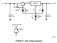
The basic idea goes back at least to NatSemi appnote AN-103 (1980), even though the basic idea then was increased output voltage:Interesting - would you please elaborate?
And using a zener on an LM317 goes back a while, too:
Using 3-pin regulators off-piste: part 1
Also discussed here.
The basic idea is the following:
78xx regulators and LM317s use a 1.25 V bandgap voltage reference. Amplifier gain is increased for higher output voltages - but so is output noise. Typical values for modern parts range from 40 µV for a 7805 to 110 µV to a 7818 (and old regs can be a lot noisier still - 10 µV per V output is not uncommon, and 79s can be at 17.5 µV / V out, for 300 µV at -18 V).
Even if a zener has e.g. 10 µV worth of noise, it's not going to matter in this scenario. You can add a capacitor in parallel if you want.
Conveniently, the GND pin will generally provide a relatively constant current of ~5 mA (78xx) or ~-1 mA (79xx), just about perfect for a zener. You can always add some current via a resistor from the output if so desired.
The protection diode as indicated in AN-103 Fig. 21 will only be required if the zener is paralleled with a capacitor as well.
Granted, this does not make for a precision voltage regulator, but for an audio device it's perfectly OK.
This whole idea is taken to an extreme by regulators like the LT3042, which uses a precision current reference so they can operate the (very low-noise) amplifier at unity gain, for a spec'd output noise of 0.8 µV.
An amplifier full of TL072s is only ever going to need moderately low-noise supplies though. Even if we say that the emitter followers are the limit for PSRR (40-50-ish dB?), we'd still not require significantly less than about 200 µV across the audio bandwidth. So the zener trick really is about as far as I'd take it (and it won't be a real problem if you are using 6 V regulators to better match available zeners if needed). The phono stage has capacitance multipliers of its own anyway.
Attachments
Last edited:
Thank you, sgrossklass. I understood the use of Zeners to increase output voltage of a given regulator, but didn't understand the noise reduction. From your detailed response, it appears there isn't really a problem that the Zener isn't a great regulator.
Thanks again.
Thanks again.
(Relatively) Modern audio amplifier circuits such as the Holman uses really are quite tolerant in terms of supplies as long as they're within limits, and a bit of temperature drift won't be an issue. There is basically nothing within them that directly depends on the exact value of supply voltages. This is essentially what having power supply rejection at DC boils down to.
There is only a handful of components in audio that are critical: DACs and ADCs need a well-defined and very clean (into the MHz) Vref (the output voltage is a multiple of Vref!), and the supply of any kind of oscillator should at least be very stable, and if it's a CMOS one low noise is also a priority.
There is only a handful of components in audio that are critical: DACs and ADCs need a well-defined and very clean (into the MHz) Vref (the output voltage is a multiple of Vref!), and the supply of any kind of oscillator should at least be very stable, and if it's a CMOS one low noise is also a priority.
Hello,
I am not sure I did understand very well. Should I replace the 78xx regulators for same recent make ? Or should I leave them live their life ?
Sgrossklass, I will not use your mod to keep the preamp as original as possible .... ;-)
But thank you very much for the explanation and use !
I am not sure I did understand very well. Should I replace the 78xx regulators for same recent make ? Or should I leave them live their life ?
Sgrossklass, I will not use your mod to keep the preamp as original as possible .... ;-)
But thank you very much for the explanation and use !
Hi I have an APT with a dead transformer, and I wonder if @GTKaudio could let me know which toroidal transformer he used Thanks Peter
Hi Peter,
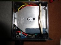
I'm almost sure I used a Triad 25VA 18x18v medical grade toroidal. I am not absolutely sure whether it was 25VA or 50VA since I was building several power supplies for other preamps and projects at the same time, and bought a 50VA Triad as well as some Hammond toroidals, but as I recall, the 25VA was the largest one I could fit into the space.
It did require that I remove the 2-prong outlets and make a bracket for the new transformer, but I didn't use or want the outlets anyway, since I use a switched power conditioner with 2 banks.
Here's the Mouser part number for the 25VA model: 553-VPM36-690
There are smaller transformers that would permit retaining the outlets, but I also wanted to increase the current handling of the transformer compared to the original.
Out of curiosity; does your transformer have black end bells, or is it an open frame with no end bells?
I suggest you also check the wiring of your fuse holder. I have come across two that did not have the fuse wired into the circuit, but were just soldered to empty terminals on the tag strip.
Cheers,
Greg
Attachments
Last edited:
Hi Greg, thanks so much for the detailed reply- great work by the way, a really neat job, though may be above my mechanical skills.
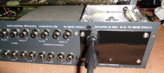
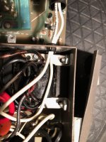
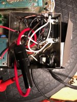
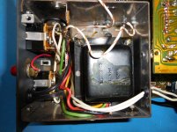
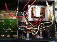
I have strong suspicion that this i not the original transformer and have attached a couple of photo's.
I had previously replaced the pig tail fuse with a fuse holder- so the circuit is complete. I disconnected the transformer outputs from the PCB and it still pulls about 0.5amp, whereas it should be less than 0.25amp. When the fuse went out the transformer and metal cage were really hot- like too hot to leave your finger on it-so I suspect that there is a short in the transformer.
I think I want to leave the power sockets on the rear, so will try and find a suitable small transformer- any thoughts?
Peter
Attachments
Hmm. I'm surprised your transformer is pulling that much current with nothing connected. The preamp draws very little when in operation.
I agree with you that your transformer may not be original. Here are the two types I've come across. It appears yours is about the same physical size, but the frame is even more minimal, and with the cloth wrap over the windings I can't tell if it's got the shielding band. Also, the wire colors are different.
If you want to use an EI transformer, it may take you awhile to find something. You definitely want a shielded transformer, even though it is mounted in its own compartment. One reason I used a toroidal was because I couldn't find a suitable EI transformer.
You might search for a lower-VA rated toroidal with a smaller diameter that would allow you to retain the outlets, but I don't know the current rating of the original transformers.
Attachments
Please scan the schematic for us. The most likely failure is a larger low voltage electrolytic cap used for the feedback decoupling typically 100uF at 10VDC.
Connect both inputs to the same source and scope compare identical points in each channel.
Shunting suspect capacitors with a similar part can find bad caps when the behavior changes with the shunted cap. Observe polarity or use a non-polar cap.
A bad capacitor will probably not create any DC voltage anomalies between channels.
Hmm. I'm surprised your transformer is pulling that much current with nothing connected. The preamp draws very little when in operation.
I agree with you that your transformer may not be original. Here are the two types I've come across. It appears yours is about the same physical size, but the frame is even more minimal, and with the cloth wrap over the windings I can't tell if it's got the shielding band. Also, the wire colors are different.
If you want to use an EI transformer, it may take you awhile to find something. You definitely want a shielded transformer, even though it is mounted in its own compartment. One reason I used a toroidal was because I couldn't find a suitable EI transformer.
You might search for a lower-VA rated toroidal with a smaller diameter that would allow you to retain the outlets, but I don't know the current rating of the original transformers.
Hi Greg,
I have my own APT that I use as a reference in the "lab", and it has the black shielded transformer in your first picture.
So yes finding a suitable replacement may be tricky- Mouser has A41-25-36L Bel Signal Transformer | Mouser
though they have no stock and it is not shielded
I am guessing the current rating is around 15VA based on the fuse size (125ma) so 25VA should be adequate, as it draws about 0.125Amp on power up and then about less than 0.1A on operation.
Peter
- Home
- Amplifiers
- Solid State
- Apt Holman preamp problem