Hello !
My late elder brother had this preamplifier on it's pile of Hifi gear. Unused. He was very big into HIFI and had a huge hifi system. So I did not bother seeing this item unused.
But this device suffer from a phono channel loudness difference. The left channel is definitely lower. It is not a turntable and cabling problem. I checked that.Left and right volumes are good if I use any entry other than the phono. The device seems not to have been touched since it left the factory.
I also cleaned all pots, adjustable and switches using KF Contact. I also checked that the problem was apparent when using the Phono #2 input.
So I decided to check inside and started to measure voltages as per the maintenance manual.
All is not good. The device is wired for 240 V (from factory) and my mains are around 235V.
The unregulated supply is at +25,5V (listed 25V) and -22.0V (Listed -25V)
The regulated power supply is at +18.0 V (listed at 18+/-0.4V) and -19V (listed at -18 +/-0.4V)
The OpAmp supply is at +15.5V and -16.2 instead of the +/-16V.
THe headphone supply is at +16.5V/-15.5V instead of the +/-16.5V.
So I looked also at the phono voltages.
The FET gate voltages are "not good" at 0.3mV on each FET. As Mr Holman specifies 0.0, I bet I've got a problem here.
I would appreciate your input on my measurements and any advice you can give me regarding the repair.
Many thanks in advance for your help !
P.S. : I started asking questions in an old thread in Analog Line Level, the thread is APT Holman preamp manual, schematics ? but as this become more involved I choose to open a new thread ...
Last edited:
Hello
Here am I again.
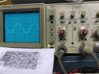
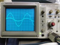
I put a 1kHz -30dB at the input of the phono preamp. And got the phono preamp output on the scope. See the picture.
The voltages are Left 1.2V and right around 4.5 V picked at the front input selector switch (easiest place to put the probes).
Last but not least, the two signals are lightly dephased.
I'm at lost here. And can't find what to do to find the default.
So all help will be appreciated !
Here am I again.
I put a 1kHz -30dB at the input of the phono preamp. And got the phono preamp output on the scope. See the picture.
The voltages are Left 1.2V and right around 4.5 V picked at the front input selector switch (easiest place to put the probes).
Last but not least, the two signals are lightly dephased.
I'm at lost here. And can't find what to do to find the default.
So all help will be appreciated !
Attachments
Are the frequency responses matched?
Hi, I'm interested in this question too: о
Hello !
I beg your pardon. The two signals are not dephased. I should use the scope more often and remember what every knob does.... I'm becoming too old....
I've checked all the voltages in the phono section. On the right channel, they are nearly spot on and a bit on the high side on the culprit left channel...
I do not see any browned resistor nor any mechanical damage. Voltages at the transistors are consistent between right and left channel.
I'm very very puzzled.
Hello,
I so feeble on electronics I can't understand what makes the gain of this amplifier and what I should look at to see if it has the proper gain.
Mr Holman is a very talented guy and devised a thing of pure beauty, but I'm waaaayyy less clever than he his ! So I can't troubleshoot this one ! He beats me. No problem.
Could you get the signal out of the tape loop so as to determine approximate gain at 1 kHz? It would be interesting to know whether the "loud" or the "quiet" channel is the faulty one.
Have you already tried feeding in the signal after the input selector switch's phono-related section, just to rule that out? Repeat at R6/106 to rule out C12/112 as well. There's also a phono balance related section on the input selector, bad contact there could reduce right channel gain as well... but you said it's the left channel that is weaker.
At the end of the day I would not be too surprised if it turned out to be a bad C13, C17 or perhaps C12... regular polar electrolytics that have been kept at the mV level for 4 decades are, in all likelihood, toast or at least in need of some serious reforming. I would only trust dedicated low leakage types like the orange Elnas from back in the day to make it, and those tended to be used in sub-10 µF sizes, not like anything in question.
It can't hurt to check solder joints on all the components in the feedback network... 7 passives per side, that should still be manageable.
Last edited:
Hello !
Yesterday, I got an Email stating that RAYMA has answered on this thread.
The post did not show on the site ???? Lost in cyberspace ?
Here it is :
---Quote (Originally by georgesgiralt)---
So the input of the phono preamp is the same for both channels. See the picture.
Rayma, the scope and probes are "perfect" for both channel. It is the phono preamp which is at fault. I can ear it so it is quite important.
---End Quote---
Very good. Now we must determine if it is a simple gain difference , or an RIAA frequency difference.
***************
I did some more tests to answer this :
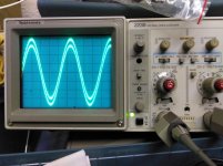
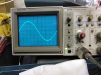
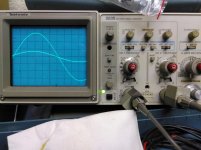
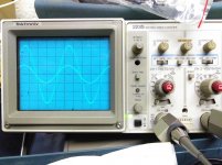
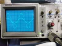
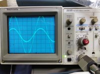
I varied the frequency of the signal generator from 50 Hz to 16 kHz. Alas, nothing significant change. See the pictures. First is 50 Hz, 100Hz, 400 Hz, 800 Hz, 4kHz, 10 kHz and 16 kHz. I omit the 1kHz because it was that frequency I previously used. I have corrected the gain of the scope to have the trace as wide as possible. Thanks for your help.
Yesterday, I got an Email stating that RAYMA has answered on this thread.
The post did not show on the site ???? Lost in cyberspace ?
Here it is :
---Quote (Originally by georgesgiralt)---
So the input of the phono preamp is the same for both channels. See the picture.
Rayma, the scope and probes are "perfect" for both channel. It is the phono preamp which is at fault. I can ear it so it is quite important.
---End Quote---
Very good. Now we must determine if it is a simple gain difference , or an RIAA frequency difference.
***************
I did some more tests to answer this :
I varied the frequency of the signal generator from 50 Hz to 16 kHz. Alas, nothing significant change. See the pictures. First is 50 Hz, 100Hz, 400 Hz, 800 Hz, 4kHz, 10 kHz and 16 kHz. I omit the 1kHz because it was that frequency I previously used. I have corrected the gain of the scope to have the trace as wide as possible. Thanks for your help.
Attachments
-
 IMG_20191017_193832.jpg747.9 KB · Views: 218
 -
 IMG_20191017_193702.jpg828.6 KB · Views: 206
 -
 IMG_20191017_193559.jpg712.8 KB · Views: 197
 -
 IMG_20191017_193614.jpg798.4 KB · Views: 163
 -
 IMG_20191017_193939.jpg735 KB · Views: 45
 -
 IMG_20191017_194005.jpg708.8 KB · Views: 43
 -
 IMG_20191017_194027.jpg819.4 KB · Views: 53
I got an Email stating that RAYMA has answered on this thread.
The post did not show on the site ???? Lost in cyberspace ?
I deleted that post after seeing that you found bad capacitors, which could be the problem. Good luck.
Hello ! The worst capacitor is C17. It has leaked and shows around 30 pF capacity. By comparison, C13 is quite new ;-)
I've replaced both and the preamp is PERFECT. (my phone did not register the image I took of the scope... Grrr)
In order to keep things symmetric, I exchanged C113 and C117 which were not bad but not pristine either...
I've refrained to change other capacitors, even if I've them.
I'll keep this for next time ...
I'm listening to it now. "La forza del destino", by Mr Verdi an RCA red Label...
Happy to have recovered this fine piece of gear !
I'll thank you ALL for your help ! I'm very bad at troubleshooting, so your help was INVALUABLE !
Thank you !
Hello,
Thanks for your help. I removed C13 (easiest for me) and tested it. It is toast. So I ordered all the phono preamp electrolytic and the power supply caps (I have nothing in stock right now). I change them and keep you posted.
Have a nice day !
I think if you had used a square wave rather than sine you would have seen a larger difference between the channels. Remember squares will give insight 1/10 to 10 times the base frequency which can be very useful for comparing response. 200Hz to 1 KHz will tell you lots.
G²
Hello,
I've another question about this preamplifier.
Given the 10 µF capacitor failed badly (leaked totally) and that there are a bunch of them inside, will it be wise to replace all of them now or wait for them to fail in the "if it is not broken, don't fix it". And the 100µF are also in the line for replacement...
Thanks for your help !
- Status
- This old topic is closed. If you want to reopen this topic, contact a moderator using the "Report Post" button.
- Home
- Amplifiers
- Solid State
- Apt Holman preamp problem