First, I do not have a particular project but am just trying to learn, but I hope that you'll still help. 🙂
Any transformer do only work if the power is AC, but there have to be a lower and upper limit. A 0.01Hz or a 15Ghz would properly not cross over, using a standard transformer, used to convert your main power?
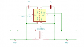
Lets say you find a transformer that can go from i.e. 100MHz to 1GHz but want to go from DC to 1GHZ, could you then put a digital isolator in parallel that goes from DC to 300MHz and expect everything from DC to 1GHz, now crossing over to the isolated circuit?
Please look at my just for giggles schematic🙂
Any transformer do only work if the power is AC, but there have to be a lower and upper limit. A 0.01Hz or a 15Ghz would properly not cross over, using a standard transformer, used to convert your main power?
Lets say you find a transformer that can go from i.e. 100MHz to 1GHz but want to go from DC to 1GHZ, could you then put a digital isolator in parallel that goes from DC to 300MHz and expect everything from DC to 1GHz, now crossing over to the isolated circuit?
Please look at my just for giggles schematic🙂
Attachments
That not work, because the two halves of the circuit would interfere with each other.
Be aware that a connection which worked from DC to 1GHz would not normally be described as isolation; it would be the exact opposite of isolation.
Be aware that a connection which worked from DC to 1GHz would not normally be described as isolation; it would be the exact opposite of isolation.
That not work, because the two halves of the circuit would interfere with each other.
Be aware that a connection which worked from DC to 1GHz would not normally be described as isolation; it would be the exact opposite of isolation.
Thanks, my idea was that you do automaticaly get an isolation by using a transformer from a few hz to maybe 1Mhz in a smps but wary low Hz and even DC do not cross over that isolation, and I imagine that there also are some upper limit.
So to let RF cross an transformer, do I imagine you have to use a transformer, designed for RF but that does still not let DC trough. So what if you desire isolation? 🙂
Transformers are normally designed to work at specific frequencies (or within a range of frequencies).
A transformer constructed using normal techniques consisting of two insulated and isolated windings that may be coupled together either on a magnetic core or via free space have galvanic isolation. They are separate.
Transformers can work down to sub hertz levels if constructed appropriately but they will NEVER pass DC.
Galvanic isolation - Wikipedia
Transformers are normally designed to work at specific frequencies (or within a range of frequencies).
A transformer constructed using normal techniques consisting of two insulated and isolated windings that may be coupled together either on a magnetic core or via free space have galvanic isolation. They are separate.
Transformers can work down to sub hertz levels if constructed appropriately but they will NEVER pass DC.
Galvanic isolation - Wikipedia
Thanks, no DC do not change the magnetic field. Therefore did I think that a digital isolator, going from let's say DC and to 300MHz and in parallel put a 100MHZ to 1GHz transformer, and would give from DC to 1GHz, but of cause is it not so easy🙂
You can pass information galvanically isolated from DC and until many GHz. The problem is that each frequency range may require different technical solutions and a wide-band solution becomes complex. You may need to combine different technical solutions to achieve a wider frequency range.
Thanks🙂 So my idea on using a 100MHz to 1GHz transformer and combine it with a digital isolator from DC to >100MHz is the right idea?You can pass information galvanically isolated from DC and until many GHz. The problem is that each frequency range may require different technical solutions and a wide-band solution becomes complex. You may need to combine different technical solutions to achieve a wider frequency range.
If you look at my small schematic, is there a way to combine these two components?
Thanks🙂 So my idea on using a 100MHz to 1GHz transformer and combine it with a digital isolator from DC to >100MHz is the right idea?
If you look at my small schematic, is there a way to combine these two components?
No, I did not say that the solution is transformers or that a simple parallel combination of transformers will work.
One possible DC-to-HF solution is a high speed optical link sending numerical information about the situation in one end of the fiber to the other end of the fiber where the information is decoded. It is technically not simple but can transfer information in quite a wide frequency range.
If you just put transformers in parallel, the transformer that is not suited for the actual frequency is likely short circuit the transformer that could transfer such a frequency.
If your principle with parallel transformers would work, why do you see a solution with wideband combined transformers advantageous over a single transformer we know will work at a frequency we know up-front?
No, I did not say that the solution is transformers or that a simple parallel combination of transformers will work.
One possible DC-to-HF solution is a high speed optical link sending numerical information about the situation in one end of the fiber to the other end of the fiber where the information is decoded. It is technically not simple but can transfer information in quite a wide frequency range.
If you just put transformers in parallel, the transformer that is not suited for the actual frequency is likely short circuit the transformer that could transfer such a frequency.
If your principle with parallel transformers would work, why do you see a solution with wideband combined transformers advantageous to a single transformer we know will work at a frequency we know up-front?
Thanks! First I am wary noob so do not know how it's normally handled🙂
Sorry did formulate my question wrong, what I meant was not if my circuit works, because that have already been answered but what I meant was if a solution with a digital isolator in some sort of combination with a transformer that was made for the purpose, could work🙂
But am I right in thinking that if you could find a single chip or a single transformer that went from below your min requerement and to a bit above, it could be done fairly simple?
So you do what Amplifier Research do in their Wideband power amps and stick em in series instead!If you just put transformers in parallel, the transformer that is not suited for the actual frequency is likely short circuit the transformer that could transfer such a frequency.
Wideband is pretty much defined by fractional bandwidth not just frequency,
100M-1Gig is only one decade, easily doable with a TLT style transformer even without any core, a 1MHz - 100MHz stage is actually much harder then a 100MHz - 1GHz stage, and the 3 decades of the audio band is actually really quite a big ask in transformer design terms.
As you drop towards DC the magnetising inductance that you want rises rapidly if you wish to keep primary current reasonable, so core sizes get LARGE fast, and of course NO transformer will ever pass DC.
That sounds like a great idea, so "just" find a (fraction Hz to 1KHz) in series with a (800Hz to 200Mhz) in series with a (100MHz to 1GHz) and all should be okay? If we say 500mA max?So you do what Amplifier Research do in their Wideband power amps and stick em in series instead!
Wideband is pretty much defined by fractional bandwidth not just frequency,
100M-1Gig is only one decade, easily doable with a TLT style transformer even without any core, a 1MHz - 100MHz stage is actually much harder then a 100MHz - 1GHz stage, and the 3 decades of the audio band is actually really quite a big ask in transformer design terms.
As you drop towards DC the magnetising inductance that you want rises rapidly if you wish to keep primary current reasonable, so core sizes get LARGE fast, and of course NO transformer will ever pass DC.
Thanks! First I am wary noob so do not know how it's normally handled🙂
Sorry did formulate my question wrong, what I meant was not if my circuit works, because that have already been answered but what I meant was if a solution with a digital isolator in some sort of combination with a transformer that was made for the purpose, could work🙂
But am I right in thinking that if you could find a single chip or a single transformer that went from below your min requerement and to a bit above, it could be done fairly simple?
I believe dmills hints a way to extend the working range of transformers. I do not know that company.
One thing you need to come up with for a good solution is a problem that the solution you have solves well.
We could perhaps imagine a more wide-band arrangement with more transformers and other elements combined. But, if we for any application where our solution could be used know simpler and technically better solutions, our solution has no purpose. This is the problem with purely imaginary exercises, that we do not know if the outcome serves any purpose.
Study the reference to a company dmills gave you and it may provide some reply to your question. When you have a specific problem to solve, perhaps we can help you.
That sounds like a great idea, so "just" find a (fraction Hz to 1KHz) in series with a (800Hz to 200Mhz) in series with a (100MHz to 1GHz) and all should be okay? If we say 500mA max?
If you could combine with success such transformers, what would you use the combination for?
You are compleatly correct, hmm... Okay here are a project that it could maybe used fore.🙂I believe dmills hints a way to extend the working range of transformers. I do not know that company.
One thing you need to come up with for a good solution is a problem that the solution you have solves well.
We could perhaps imagine a more wide-band arrangement with more transformers and other elements combined. But, if we for any application where our solution could be used know simpler and technically better solutions, our solution has no purpose. This is the problem with purely imaginary exercises, that we do not know if the outcome serves any purpose.
Study the reference to a company dmills gave you and it may provide some reply to your question. When you have a specific problem to solve, perhaps we can help you.
I have as scope that goes up to 350MHz. It can take up to 400V, so no need for protecting it against high Voltage when I max will measure 50V. It has common ground on all 4 ch so to avoid blowing it up or to avoid cross talk between the channels, an isolator would be perfect.
You are compleatly correct, hmm... Okay here are a project that it could maybe used fore.🙂
I have as scope that goes up to 350MHz. It can take up to 400V, so no need for protecting it against high Voltage when I max will measure 50V. It has common ground on all 4 ch so to avoid blowing it up or to avoid cross talk between the channels, an isolator would be perfect.
I will now be the devils advocate: A logical use as a signal isolator, but have you thought about the input impedance of such a transformer combination? Transformers will obviously not transfer DC, but AC OK. Have you thought about the size if one transformer can do sub-Hz transfer? Why do you need GHz transfer speed for your oscilloscope? A normal isolation amplifier ranging until 50-100MHz should do and would be more precise?
Yep, you wont get high impedance inputs from such a lash up, and it will likely not be very flat in either frequency or phase response, doesn't matter much in ARs typical applications.
I would note that nobody who cares about the action above a few tens of MHz should be using high Z probes (Unless they are active ones), 50R with a source terminating resistor is so much better behaved in basically all ways.
Scopes do not have a particularly extreme linearity requirement, so I might be thinking linear opto coupler (The type with a feedback diode) or such. Transformer is probably wrong for this.
I do sometimes find myself doing things like winding a whole mess of miniature coax on an ungapped ETD59 to make a ultra wideband common mode choke, no isolation as such, but it works well enough for many applications.
Regards, Dan.
I believe FriedMule's suggestion for a use was good. FriedMule is aiming at constructing the almost perfect AC transformer. A very relevant aim that has been pursued by millions of people through time.
When we believe to have an exceptional idea, it is sometimes useful to imagine a relevant use and from that use investigate how the problem our idea solves was solved before. Disappointingly, other have in most situations found solutions before that in many cases are also simpler. That happens in a large part of the cases because when millions of people look for a solution to the same problem, some very often find a solution before us.
FriedMule, it was a good proposal for a use. The underlying feeling of a solution with more parallel transformers is intuitively logical. Unfortunately when you look into the details, the solution looks less ideal. But unless we keep thinking about new ways to solve a problem, we will never find one and that we have to be disappointed most of the times, is an inherent part of that game.
In the start was it just a question to try to learn about it, butt as one rightly wrote, it would be better if I changed my thought experiment to a concrete project, so I thought of one that really would help me, but of cause do we no longer talk about any need for 1GHz🙂I will now be the devils advocate: A logical use as a signal isolator, but have you thought about the input impedance of such a transformer combination? Transformers will obviously not transfer DC, but AC OK. Have you thought about the size if one transformer can do sub-Hz transfer? Why do you need GHz transfer speed for your oscilloscope? A normal isolation amplifier ranging until 50-100MHz should do and would be more precise?
I have not thought the project to end but I know that there is a lot to consider, and I am still a noob. 🙂
Is a optocoupler not to slow and unlinear? Does it not also loose it's precision over a few years? May a digital isolator not be better suited?Yep, you wont get high impedance inputs from such a lash up, and it will likely not be very flat in either frequency or phase response, doesn't matter much in ARs typical applications.
I would note that nobody who cares about the action above a few tens of MHz should be using high Z probes (Unless they are active ones), 50R with a source terminating resistor is so much better behaved in basically all ways.
Scopes do not have a particularly extreme linearity requirement, so I might be thinking linear opto coupler (The type with a feedback diode) or such. Transformer is probably wrong for this.
I do sometimes find myself doing things like winding a whole mess of miniature coax on an ungapped ETD59 to make a ultra wideband common mode choke, no isolation as such, but it works well enough for many applications.
Regards, Dan.
Yes now where we are going from a thought project, it may be a wrong solution to use transformers, but what if I have 15V or even 40V P/P?
Oh thanks, what a nice and great way to say it!🙂I believe FriedMule's suggestion for a use was good. FriedMule is aiming at constructing the almost perfect AC transformer. A very relevant aim that has been pursued by millions of people through time.
When we believe to have an exceptional idea, it is sometimes useful to imagine a relevant use and from that use investigate how the problem our idea solves was solved before. Disappointingly, other have in most situations found solutions before that in many cases are also simpler. That happens in a large part of the cases because when millions of people look for a solution to the same problem, some very often find a solution before us.
FriedMule, it was a good proposal for a use. The underlying feeling of a solution with more parallel transformers is intuitively logical. Unfortunately when you look into the details, the solution looks less ideal. But unless we keep thinking about new ways to solve a problem, we will never find one and that we have to be disappointed most of the times, is an inherent part of that game.
I was just thinking, that if a transformer alone could not do the job, why not combine several solutions in one circuit🙂
- Home
- Design & Build
- Construction Tips
- Just trying to learn - DC/AC isolation