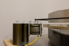
I made a very simple test bed: an Arduino which outputs 3 PWM sinewaves at 120deg, a low pass filter, 3 x 7293 Chinese amps on which i replaced 2 of the 3 fake 7293s with real ones, 3 x 18VA transformers 9v - 220v.
Everything works fine not counting the tremendous heat the amps generate. I was under the impression the Papst motor consumes about 30W, which when split 3 ways should not cause any significant issues, but this is not the case in practice. The entire setup draws 190W from the wall and the sinks become really hot.
Any ideas why this should be? Apparently the chip amps do not enjoy the load through the step up transformers. They currently run at around 70v at each transformer's output.
What is even stranger is that previously it ran with a single sinewave from the same setup, split across 2 amp channels and two transformers with a phase splitting cap by the motor and while it was getting a bit hot, it was a far cry from the current oven.
Awaiting class D amps atm, but not really looking forward to having an AM transmitter next to the turntable.
Thanks for any suggestions.
Attachments

Try an rc filter after the Arduino. Aim for a sub 100hz corner. I got a similar setup working ok. It didn't get hot.
Yes, the PWM clock frequency might be way too high for this setup, possibly leading the chips into cross conduction.
OTOH I see a motor (from an old tape machine, maybe?) that is designed to operate on a single phase AC voltage with a 4 µF run capacitor. Hence it's windings aren't exactly designed for 3 phase 120 deg. supply.
Best regards!
OTOH I see a motor (from an old tape machine, maybe?) that is designed to operate on a single phase AC voltage with a 4 µF run capacitor. Hence it's windings aren't exactly designed for 3 phase 120 deg. supply.
Best regards!
I see a motor (from an old tape machine, maybe?) that is designed to operate on a single phase AC voltage with a 4 µF run capacitor. Hence it's windings aren't exactly designed for 3 phase 120 deg. supply.
This is an interesting theory that i am not capable of disproving. The motor is out of an Empire turntable and is indeed meant to work with a phasing cap, but this alone does not mean much as it is a simple way to operate 3-phase motors off a single phase.
The only reason i believe the Papst to be a delta connected 3-phase motor is from whatever i have read on the net.
Sorry, but the delta wound Papst motors are most definitely suitable for a three phase supply. They are however notoriously inefficient.
I use mine, a little bigger than the one in the picture, with 3 x 60VA transformers, driven by 3 x 100W class D amplifiers.
I use mine, a little bigger than the one in the picture, with 3 x 60VA transformers, driven by 3 x 100W class D amplifiers.
Last edited:
I use mine, a little bigger than the one in the picture, with 3 x 60VA transformers, driven by 3 x 100W class D amplifiers.
Thanks for this, makes a lot of sense. Just tried running off a single phase with a cap and the power consumption dropped from nearly 200W to 75W. Not sure if this is what should be expected. Seems very strange.
The 75W looks reasonable. Motor uses 20W, winding resistance wastes 10W and the rest goes towards class AB amp and mains transformer efficiency.
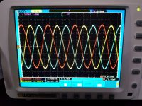
For some reason the delta connected motor applies a much heavier load on the amps than the single phase with a cap. The sinusoidal waveshape at the amps outputs is very distorted even at low voltage levels which makes me think the reflected load is well below 4ohms. Interestingly, all 3 amps show a different level of distortion.
OK, not sure if this extreme simplification works, please don't laugh.
Motor draws nearly 200mA @100v which represented by a simple resistor would be 500R. The transformer has 200ohm of winding resistance and a ratio of 24. Which means that 700ohms are seen from the amps as 1.21R.
Bigger transformers may have negligible wire resistance which would only make matters worse.
The conclusion seems obvious: use step-up transformers with a much lower ratio. 1:10 would mean a 7ohm load.
Any thoughts if the reasoning above is faulty?
Maybe because it is NOT the assumed delta connected 3 phase motor but just a single phase motor meant for use with a 4 uF capacitor? Maybe it is a single phase motor meant to be used with a 4 uF cap as printed on the motor itself and explains the 200W power consumption ìnstead of 75W when used 3 phase at least something?
Maybe assuming stuff is not the best recipe for success?
Maybe assuming stuff is not the best recipe for success?
Last edited:
Maybe because it is NOT the assumed delta connected 3 phase motor
Dunno. Perhaps someone who knows about motors would know if the external rotor Papst does have a dual phase variant. Or whether an external rotor motor can be anything but 3 phase. Fwiw i measure exactly the same resistance and inductance between any two wires.
I would look up the specifications of that exact motor or send an email to Papst if they can tell you if you can use this product out of specs. I can imagine their answer though when you mention it uses only 200W when fed 3 phase power 🙂
Can you mention the type number? Otherwise we are in "can I use my Diesel car on gasoline?" area.
Can you mention the type number? Otherwise we are in "can I use my Diesel car on gasoline?" area.
Last edited:
Sure. It is HSM 14.50-4-675D, exactly as the one discussed in the thread below. It did not cross my mind to measure the phase angle when using a cap, but his measurement looks interesting and almost conclusive.
Papst motor Guru help- Vinyl Engine
Papst motor Guru help- Vinyl Engine
The motor clearly says 4µF cap, so you will need a 90° out of phase signals for driving the motor, but usually in non-reversible motors, the start coil has higher resistance than the the run coil, so, imbalance in loads for the amps will be expected.
There are three phase synchronous and asynchronous motors as well as two phase hysteresis synchronous »Außenläufer« motors. Your document covers the latter ones. The OP's motor also is a single phase hysteresis synchronous one.
Best regards!
Best regards!
Fixed the transformer issue and now all 3 phases get an undistorted waveform. The power consumption did go down to 164W due perhaps to the improved waveform.
It seems Kay Pirinha and Jean-Paul are correct and the internet wrong about this particular motor 🙂
Until i find a proper 3-phase motor i shall change the oscillator code to dual phase @90deg.
Thanks to everyone for the useful discussion.
It seems Kay Pirinha and Jean-Paul are correct and the internet wrong about this particular motor 🙂
Until i find a proper 3-phase motor i shall change the oscillator code to dual phase @90deg.
Thanks to everyone for the useful discussion.
It is a simple matter of following the manufacturers recommendations instead of believing internet blah blah. If it is german technology there is a very high risk of correct information by the manufacturer.
The 200W power consumption would be enough to know something is not OK. If anyone states that Papst motors are notoriously inefficient I can imagine why when they are used like this. I use Papst on a daily basis and the products I know are fine examples of good engineering. In fact their current series EC fans are among the most power efficient fans in the world.
The 200W power consumption would be enough to know something is not OK. If anyone states that Papst motors are notoriously inefficient I can imagine why when they are used like this. I use Papst on a daily basis and the products I know are fine examples of good engineering. In fact their current series EC fans are among the most power efficient fans in the world.
Last edited:
It is a simple matter of following the manufacturers recommendations instead of believing internet blah blah.
Go on, rub it in 🙂
In my defense i have never heard of any old turntable or tape deck motors being 3-phase driven in their original setups. And yet, some apparently are 3-phase.
Btw, just measured the phase shift with the manufacturer's recommended 4uF cap. It is spot on 60deg. Not sure what sense to make out of this. So this motor is not supposed to be driven at 90deg between the phases? With a more appropriate transformer power consumption in this connection dropped to 45W.
Sorry, my knowledge of motors is around zero and the incentive to improve it is low. It was a one off experiment, centered mostly around the micro.
- Home
- Source & Line
- Analogue Source
- Help driving a 3-phase Papst ausenlaufer