Hello Sub builders...
I have settled on a new mini project consisting of a BMS 12S300 in a very low tuned enclosure... BMS Specifies a 60L container for the given response with 110 mm / 517 mm long (presumably) circular port..

I would like a slot designed port and given my confused state i can't seem to find anyone coming up with definitive calculations for getting the correct port length etc.. maybe i am missing something. I have a rumour in my head the WinISD doesn't calculate specifically slotted ports.. maybe i'm being corrupted by something somewhere else on DIY.
BMS Recommends to use a port length almost half the size of mine and a circular cross section of 9500mm2, again thats almost half as much as my 21840mm2 (6X36X102cm) slot port.

Given the simulated response i just don't think i am getting the SPL i should be getting considering this type of driver... it has a super low FS. I have already tried to get more SPL out of the enclosure by increasing the volume by 8 litres...

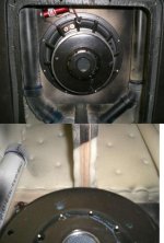
I have attached some pictures of the simulated response with WinISD and some pictures of the enclosure... my instinct tells me that the port length is two small in width and too long in its entire length to the back.
The parameters as follows....
BOX = 67.8 L
Tuning Freq = 29Hz
VENTS = 6cm X 36.4cm
Calculated Vent Length = 102cm
1st port resonance 167hz (A bit undesirably low... LPF will be set around this point)

After putting together the box in CAD and calculating the volume displacement with the amp modules am i accounting for the rear volume independent of the port volume? i have tried to balance this with the suggested port length 102cm X width and size to somehow find the balance with a slotted port that will fit in unison with the suggested internal 67.8L.

Are there any subwoofer building experts out there that could at least help me approve what i have done as a valid design? I feel that i am overthinking things when in reality it could quite possibly be a bit more straight forward..
I really would appreciate any help where you can,
Lots of Kind Regards,
Dec
I have settled on a new mini project consisting of a BMS 12S300 in a very low tuned enclosure... BMS Specifies a 60L container for the given response with 110 mm / 517 mm long (presumably) circular port..
I would like a slot designed port and given my confused state i can't seem to find anyone coming up with definitive calculations for getting the correct port length etc.. maybe i am missing something. I have a rumour in my head the WinISD doesn't calculate specifically slotted ports.. maybe i'm being corrupted by something somewhere else on DIY.
BMS Recommends to use a port length almost half the size of mine and a circular cross section of 9500mm2, again thats almost half as much as my 21840mm2 (6X36X102cm) slot port.
Given the simulated response i just don't think i am getting the SPL i should be getting considering this type of driver... it has a super low FS. I have already tried to get more SPL out of the enclosure by increasing the volume by 8 litres...
I have attached some pictures of the simulated response with WinISD and some pictures of the enclosure... my instinct tells me that the port length is two small in width and too long in its entire length to the back.
The parameters as follows....
BOX = 67.8 L
Tuning Freq = 29Hz
VENTS = 6cm X 36.4cm
Calculated Vent Length = 102cm
1st port resonance 167hz (A bit undesirably low... LPF will be set around this point)
After putting together the box in CAD and calculating the volume displacement with the amp modules am i accounting for the rear volume independent of the port volume? i have tried to balance this with the suggested port length 102cm X width and size to somehow find the balance with a slotted port that will fit in unison with the suggested internal 67.8L.
Are there any subwoofer building experts out there that could at least help me approve what i have done as a valid design? I feel that i am overthinking things when in reality it could quite possibly be a bit more straight forward..
I really would appreciate any help where you can,
Lots of Kind Regards,
Dec
Maybe this will help: https://www.diyaudio.com/forums/att...-dayton-port-length-effective-port-length-jpg
GM
GM
Hello Sub builders...
Given the simulated response i just don't think i am getting the SPL i should be getting considering this type of driver... it has a super low FS. I have already tried to get more SPL out of the enclosure by increasing the volume by 8 litres...
Unfortunately, the relationship between Fs and efficiency is a cubic one, so even a modest reduction in Fs results in a big loss in efficiency. Raising Vb will get you more output around the tuning frequency but doesn't change the underlying efficiency of the driver itself. Also, the lower you tune a vented box the less power it takes to reach Xmax in the main passband, again limiting max SPL in a low tuned box.
After putting together the box in CAD and calculating the volume displacement with the amp modules am i accounting for the rear volume independent of the port volume?
Yup, Vb in WinISD is net of all inclusions, so it's the volume left over after accounting for the port, backside of the driver, bracing, amp modules (if built into the speaker box) etc etc.
HTH,
David.
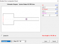
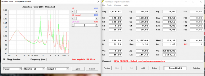
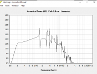
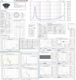
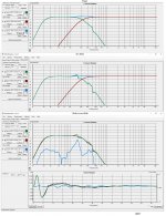
Sim in 2pi with hornresp at 120w (31v) to limit excursion to +/- 8mm :
capture 1 response. +/- 45cm depth simed, hear you see box resonnance effect that will need some damping.
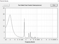
Capture 2 is port velocity at this power. It's seems me a bit high, but ok...
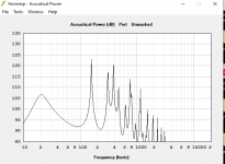
Capture 3 port output to show it first resonnance spike, at +/- 170 hz
Capture 4 is the effect of adding a simple stub of 8cm diameter to put at half lengh of the port, that is heavily stuffed, of 45cm lengh, to null the ugly 170 hz port resonnance and, the distortion it would involve of H2 at 85hz and H3 at 56hz.
Capture 5 show the stub sim shematic.
capture 1 response. +/- 45cm depth simed, hear you see box resonnance effect that will need some damping.
Capture 2 is port velocity at this power. It's seems me a bit high, but ok...
Capture 3 port output to show it first resonnance spike, at +/- 170 hz
Capture 4 is the effect of adding a simple stub of 8cm diameter to put at half lengh of the port, that is heavily stuffed, of 45cm lengh, to null the ugly 170 hz port resonnance and, the distortion it would involve of H2 at 85hz and H3 at 56hz.
Capture 5 show the stub sim shematic.
Attachments
Last edited:
Maybe this will help: https://www.diyaudio.com/forums/att...-dayton-port-length-effective-port-length-jpg
Thanks
GM
I have seen this already but struggled to decode the message.. i can see the end corrections etc.
Given the volume of my enclosure without the port for now is that sufficient, before i even get to the port. i have had to design it larger to account for fitting the slot port.
Regards
Dec
GM
Sim in 2pi with hornresp at 120w (31v) to limit excursion to +/- 8mm :
capture 1 response. +/- 45cm depth simed, hear you see box resonnance effect that will need some damping.
Capture 2 is port velocity at this power. It's seems me a bit high, but ok...
Capture 3 port output to show it first resonnance spike, at +/- 170 hz
Capture 4 is the effect of adding a simple stub of 8cm diameter to put at half lengh of the port, that is heavily stuffed, of 45cm lengh, to null the ugly 170 hz port resonnance and, the distortion it would involve of H2 at 85hz and H3 at 56hz.
Capture 5 show the stub sim shematic.
I have to admit, papa... i am not the best expert in horn resp, so unfortunately i cant imagine how these graphs translate into a type/box/enclosure.
What can you tell me from my existing designs?
Thanks
Declan
It's your cab I simed, in hornresp. Just added a long stub at half length of your port to damp first port resonnance in last two pictures.
Low frequency Q would need Eq too and high pass to protect speaker from over excursion.
I would prefer bandpass design for such a speaker, but it add some complexity and tweaking to make it right. So exept the port resonnance problem, this is a good design for the conservative simed output (120w). It would need more bracing since it s for such low frequencies.
Last edited:
It's your cab I simed, in hornresp. Just added a long stub at half length of your port to damp first port resonnance in last two pictures.
Low frequency Q would need Eq too and high pass to protect speaker from over excursion.
I would prefer bandpass design for such a speaker, but it add some complexity and tweaking to make it right. So exept the port resonnance problem, this is a good design for the conservative simed output (120w). It would need more bracing since it s for such low frequencies.
Thank you for taking the time to place in the parameters, it's helpful to see.. I need to finalise the designs today to get the wood sent off for CNC. Trying to settle on getting the most low end/output out of this driver.
Any other enclosure suggestions are welcome.
Thanks
Dec
I have seen this already but struggled to decode the message.. i can see the end corrections etc.
Given the volume of my enclosure without the port for now is that sufficient, before i even get to the port. i have had to design it larger to account for fitting the slot port.
Regards
Dec
OK, so what the equations GM provided are dealing with is a factor called End Correction (apologies if I'm covering stuff you already know - I just feel explanations usually work better with a bit of background).
So, a normal port, mounted on a baffle, with its backside in the middle of the cabinet, behaves reasonably predictably as far as modelling its length.
With anything other that that scenario, the different conditions at the back end of the port change how the air at the end of the port behaves a little. End Correction is a factor added into the equation to calculate the port length to account for this.
Unfortunately, WinISD only calculates that standard scenario properly.
The more that you have any of the walls of the port extending beyond the "nominal" port end, the longer the port will behave. A slot port is about the maximum example of this - 3 out of 4 port walls (ie the sides and base of the cab, typically) are a lot longer than the shelf itself.
So the best thing to do with the info given by GM is throw it into a spreadsheet and instead of using the 102cm predicted by WinISD, use the revised (and shorter) port length you will get from that.
Something like this should do it: Port End Correction.xlsx - Google Drive
You need to input the port dimensions, number and box info and it'll calculate the new length for you - don't overwrite the bolded cells or it won't work.
HTH,
David.
Sim in 2pi with hornresp at 120w (31v) to limit excursion to +/- 8mm :
capture 1 response. +/- 45cm depth simed, hear you see box resonnance effect that will need some damping.
Capture 2 is port velocity at this power. It's seems me a bit high, but ok...
Capture 3 port output to show it first resonnance spike, at +/- 170 hz
Capture 4 is the effect of adding a simple stub of 8cm diameter to put at half lengh of the port, that is heavily stuffed, of 45cm lengh, to null the ugly 170 hz port resonnance and, the distortion it would involve of H2 at 85hz and H3 at 56hz.
Capture 5 show the stub sim shematic.

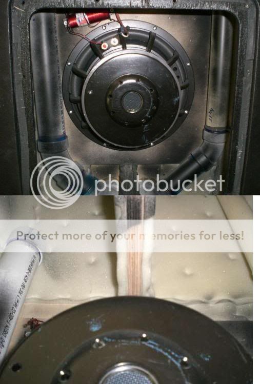
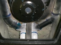
I have placed the stub your talking of in the enclosure, is this what you were suggesting? (check attachment photo)
Cylindrical in nature and governs the width of the port, 8CM in diameter, presumably that acts as an acoustical notch filter... interesting to see how this may work.
Thanks
D
OK, so what the equations GM provided are dealing with is a factor called End Correction (apologies if I'm covering stuff you already know - I just feel explanations usually work better with a bit of background).
So, a normal port, mounted on a baffle, with its backside in the middle of the cabinet, behaves reasonably predictably as far as modelling its length.
With anything other that that scenario, the different conditions at the back end of the port change how the air at the end of the port behaves a little. End Correction is a factor added into the equation to calculate the port length to account for this.
Unfortunately, WinISD only calculates that standard scenario properly.
The more that you have any of the walls of the port extending beyond the "nominal" port end, the longer the port will behave. A slot port is about the maximum example of this - 3 out of 4 port walls (ie the sides and base of the cab, typically) are a lot longer than the shelf itself.
So the best thing to do with the info given by GM is throw it into a spreadsheet and instead of using the 102cm predicted by WinISD, use the revised (and shorter) port length you will get from that.
Something like this should do it: Port End Correction.xlsx - Google Drive
You need to input the port dimensions, number and box info and it'll calculate the new length for you - don't overwrite the bolded cells or it won't work.
HTH,
David.
David, That is so helpful. That's precisely what i was looking for as there is ecfactor in winISD but it doesn't seem to do anything. I read about it somewhere else, you providing the spreadsheet is initially really helpful.
I will tinker around with this quite happily to see what comes up.
Kind Regards
Dec
OK, so what the equations GM provided are dealing with is a factor called End Correction (apologies if I'm covering stuff you already know - I just feel explanations usually work better with a bit of background).
So, a normal port, mounted on a baffle, with its backside in the middle of the cabinet, behaves reasonably predictably as far as modelling its length.
With anything other that that scenario, the different conditions at the back end of the port change how the air at the end of the port behaves a little. End Correction is a factor added into the equation to calculate the port length to account for this.
Unfortunately, WinISD only calculates that standard scenario properly.
The more that you have any of the walls of the port extending beyond the "nominal" port end, the longer the port will behave. A slot port is about the maximum example of this - 3 out of 4 port walls (ie the sides and base of the cab, typically) are a lot longer than the shelf itself.
So the best thing to do with the info given by GM is throw it into a spreadsheet and instead of using the 102cm predicted by WinISD, use the revised (and shorter) port length you will get from that.
Something like this should do it: Port End Correction.xlsx - Google Drive
You need to input the port dimensions, number and box info and it'll calculate the new length for you - don't overwrite the bolded cells or it won't work.
HTH,
David.
Hello again David,

With your spreadsheet i have come up with the new calculations for port length whilst trying to keep the volume displaced by the new port at 67.8L

Displacement with total components (Subwoofer/Plate Amp/Baffle)
= 4.49L

72.32L - 4.49L
New Rear Volume with port length at 78.2cm is 67.83L
Your calculator suggests 77.77cm long, is 78.2cm a detrimental deviation?
It was a lot of fiddling but i have it in a good balance i think. I don't want to be focussing too much on the data fastidiously as i don't think exact number always behave the way predicted.. that said your calculator on end correction has saved me a pretty good deal in box size.
Kind Regards
Dec
Here a stub done professionnally to damp a tapped horn resonnance (danley dts-20) :View attachment 789469
I have placed the stub your talking of in the enclosure, is this what you were suggesting? (check attachment photo)
Cylindrical in nature and governs the width of the port, 8CM in diameter, presumably that acts as an acoustical notch filter... interesting to see how this may work.
Thanks
D
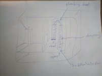
You can do really simply like in the ugly attached scheme 😉...
Attachments
New Rear Volume with port length at 78.2cm is 67.83L
Your calculator suggests 77.77cm long, is 78.2cm a detrimental deviation?
Half a cm of vent length will make only a few tenths of a Hz difference in tuning frequency, so you would be fine to ignore such a small difference.
Likewise, if making the vent the exact modelled length resulted in half a litre or so difference in internal volume, that would again make only tenths of a dB difference in LF output, so could be safely ignored.
Real life variations such as parameter tolerances in the driver itself will easily swamp those differences, so I think you're right not to worry about getting too bogged down in the detail from the model.
Just because a modelling program is capable of giving us predictions to tenths or even hundredths of a dB/Hz, doesn't mean that's relevant in the real world.
Here a stub done professionnally to damp a tapped horn resonnance (danley dts-20) :
Good ol' photobucket!
Attachments
It have been used as illustrative so much time in Just A Guy times ^^Good ol' photobucket!
Thanks David, this sort of obsessive thinking gets be bogged down with numbers and predicted measurements making me extremely reluctant on committing on getting the CAD files to the CNC operator.Half a cm of vent length will make only a few tenths of a Hz difference in tuning frequency, so you would be fine to ignore such a small difference.
Likewise, if making the vent the exact modelled length resulted in half a litre or so difference in internal volume, that would again make only tenths of a dB difference in LF output, so could be safely ignored.
Real life variations such as parameter tolerances in the driver itself will easily swamp those differences, so I think you're right not to worry about getting too bogged down in the detail from the model.
Just because a modelling program is capable of giving us predictions to tenths or even hundredths of a dB/Hz, doesn't mean that's relevant in the real world.
I have also considered using a punisher sub

It’s a pretty expensive driver but has considerably more Xmax.. I also considered the LAB 12 sub from eminence, it’s just a bit less sensitive and too little power for my 1KW module.
I remember reading somewhere that the Xmax on the BMS is a geometrical value, not sure what that means. Apparently the Xmax measurements are only 8MM, for the surround having such “give” I can’t imagine that’s all it can push.
Looking at the specs for the BMS It has a magnetic gap depth of 10mm. It’s linear excursion is 8mm and for the eminence and ciare around 14mm.
Someone correct me if I’m wrong, My guess is that the inertia on the cone over throwing the gap contributes to linear excursion before distortion, be that the BMS cone is lighter therefor less inertia when exceeding the gap depth giving its maximum linear excursion around 8mm however the lighter cone gives higher sensitivity overall at 96db vs the Ciare SW12.00 92dB & L12 89dB.
The Ciare has a larger voice coil and more power to make up for the sensitivity lost vs the BMS + more Xmax at 14mm, again given the relationship to the air gap that is 10mm presumably the cone inertia over throws and makes up for it. I guess the gap has to go deeper to prevent the coil hitting the back. My only hunch for maximum linear excursion is a guess that Ciare are measuring at a particular frequency that equals the drivers Fs as a 10mm gap depth and 14mm linear excursion don’t make sense. The resonant frequency of the BMS is lower, guessing the spider being less stiff and the lighter cone.
So I think the Ciare is a better option, will just have to adjust the port width to tame the air velocity in turn the enclosure volumes etc.
I came to some realizations whilst writing this so sorry if I answered my own questions, if anyone can confirm my thinking correct that would be marvelous.
Kind regards
Dec
Xmax specs
Hi Dec,
Ivan Beaver of Danley Sound Labs is fond of pointing out "The nice thing about specifications is that there's so many to choose from", and Xmax is one of them.
Quick recap of the geometry of a typical loudspeaker...

As can be seen, the voice coil sticks out both in front of and behind the top plate of the magnet. This means it can move back and forth without changing the amount of the voicecoil that's actually immersed in the magnetic field at any given time.
The simplest way of calculating how far the coil can move is therefore (Hc-Hg)/2 where Hc is height of the coil and Hg the height of the magnetic gap (ie top plate). This is the calculation BMS use, and it's also the most conservative.
However, the magnetic field doesn't just stop dead in line with the edge of the top plate (gap) in the magnet - you'll remember if you've ever seen demonstrations with iron filings on paper above a magnet that the field lines bulge out in curves.
That means there is some degree of usable magnetic field a bit further out, so the speaker doesn't just stop working as soon as the coil goes past that point. Particularly in the PA world therefore, where maximum volume is considered a bit more important than in say HiFi, most manufacturers use a version of Xmax calculated with extra length added to the basic version above. Most commonly it's an extra 1/4 of Hg that's added, though some use 1/3 for an even more optimistic value.
This is the method that Ciare use, which is part of why their figure is so much higher.
There are other methods too - one being to measure distortion and pick a limit that is deemed acceptable - 10% total harmonic distortion is one of the more common versions of this threshold - which is what I believe Eminence use. Unfortunately I don't know how closely that correlates to either of the other methods but I believe it's closer to the latter, more extended one.
So, if we were to compare the drivers "like for like" we'd end up with something like this:

Best thing for you to do is look at them all in WinISD or whatever other modelling program you prefer - try and balance out the enclosure size, vent lengths, power requirements (remember you don't have to use all 1000W of your module if it's already loud enough with less power) and driver excursion.
FWIW, here's the predicted SPL for each when driven to the highest interpretation of Xmax in each case, in your original 68l tuned to 29Hz:

Couple of points to note:
1: The maximum difference in SPL is only 3dB, which is really not a huge difference at all. Indeed, as a rough rule of thumb, 3dB is about the smallest difference that a non-critical listener (eg guest at a party) is likely to notice at all.
2: The Ciare and BMS have similar response shapes, so should sound similar - the Eminence is a bit different. It would need a much bigger box if you wanted to get a more similar response shape, albeit if you've got EQ available this isn't so much of an issue.
3: Louder equals higher vent airspeed, meaning you may need a bigger vent, increasing the overall size of your final box.
4: The Ciare needs 78V (~750W at a nominal 8Ω), the LAB12 42V (~220W @ 8Ω) and the BMS 50V (~310W @ 8Ω) to reach the given SPL's so in every case your amp module will have a bit of headroom.
If it were my choice, and SPL was an absolute priority, I might choose the Ciare with a bigger vent, but in any other circumstance, I'd live perfectly happily with the BMS, keeping the smaller vent and using the £40-odd saved for a nice meal out 😉
HTH,
David.
I have also considered using a punisher sub
View attachment 789886
It’s a pretty expensive driver but has considerably more Xmax.. I also considered the LAB 12 sub from eminence, it’s just a bit less sensitive and too little power for my 1KW module.
I remember reading somewhere that the Xmax on the BMS is a geometrical value, not sure what that means. Apparently the Xmax measurements are only 8MM, for the surround having such “give” I can’t imagine that’s all it can push.
Hi Dec,
Ivan Beaver of Danley Sound Labs is fond of pointing out "The nice thing about specifications is that there's so many to choose from", and Xmax is one of them.
Quick recap of the geometry of a typical loudspeaker...
As can be seen, the voice coil sticks out both in front of and behind the top plate of the magnet. This means it can move back and forth without changing the amount of the voicecoil that's actually immersed in the magnetic field at any given time.
The simplest way of calculating how far the coil can move is therefore (Hc-Hg)/2 where Hc is height of the coil and Hg the height of the magnetic gap (ie top plate). This is the calculation BMS use, and it's also the most conservative.
However, the magnetic field doesn't just stop dead in line with the edge of the top plate (gap) in the magnet - you'll remember if you've ever seen demonstrations with iron filings on paper above a magnet that the field lines bulge out in curves.
That means there is some degree of usable magnetic field a bit further out, so the speaker doesn't just stop working as soon as the coil goes past that point. Particularly in the PA world therefore, where maximum volume is considered a bit more important than in say HiFi, most manufacturers use a version of Xmax calculated with extra length added to the basic version above. Most commonly it's an extra 1/4 of Hg that's added, though some use 1/3 for an even more optimistic value.
This is the method that Ciare use, which is part of why their figure is so much higher.
There are other methods too - one being to measure distortion and pick a limit that is deemed acceptable - 10% total harmonic distortion is one of the more common versions of this threshold - which is what I believe Eminence use. Unfortunately I don't know how closely that correlates to either of the other methods but I believe it's closer to the latter, more extended one.
So, if we were to compare the drivers "like for like" we'd end up with something like this:
Best thing for you to do is look at them all in WinISD or whatever other modelling program you prefer - try and balance out the enclosure size, vent lengths, power requirements (remember you don't have to use all 1000W of your module if it's already loud enough with less power) and driver excursion.
FWIW, here's the predicted SPL for each when driven to the highest interpretation of Xmax in each case, in your original 68l tuned to 29Hz:
Couple of points to note:
1: The maximum difference in SPL is only 3dB, which is really not a huge difference at all. Indeed, as a rough rule of thumb, 3dB is about the smallest difference that a non-critical listener (eg guest at a party) is likely to notice at all.
2: The Ciare and BMS have similar response shapes, so should sound similar - the Eminence is a bit different. It would need a much bigger box if you wanted to get a more similar response shape, albeit if you've got EQ available this isn't so much of an issue.
3: Louder equals higher vent airspeed, meaning you may need a bigger vent, increasing the overall size of your final box.
4: The Ciare needs 78V (~750W at a nominal 8Ω), the LAB12 42V (~220W @ 8Ω) and the BMS 50V (~310W @ 8Ω) to reach the given SPL's so in every case your amp module will have a bit of headroom.
If it were my choice, and SPL was an absolute priority, I might choose the Ciare with a bigger vent, but in any other circumstance, I'd live perfectly happily with the BMS, keeping the smaller vent and using the £40-odd saved for a nice meal out 😉
HTH,
David.
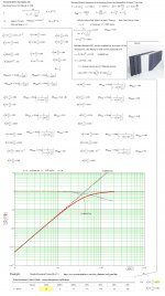
Hi All,
FYI:
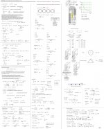
If you want to interface a Circular Stub to a Slot-Port: You should first calculate the equivalent Hydraulic Diameter for your intended Slot-Port Area and make equal to a corresponding Circular Entrance that is placed centered(middle)
to the Slot-Port if the Slot CSA Ratio is equal or less than 2/1 but if > than 2:1, consider to add Slot CSA Dividers.
Your suggested Slot has a CSA Aspect Ratio of 36.4/6= ~6.07/1 so in order to keep the Ratio below ~2/1 you need at least 3 Dividers:
Then 3 Circular Stubs should be used perpendicular to the 3 Dividing Slot Areas.
Always calculate the required Stuffing needed to control the Stub Q+anti Pressure Level and try to make the individual interfacing Stubs total Hydraulic Area as close as possible to the sum of the calculated Slot-Port Hydraulic input Areas/ # of divided Areas( Suggested here: # =3).
Tapering the Stub is also an option.
See the submitted example Picture where calculations are made to improve a Slot-Port that was too wide(=LF HOM Generator).
b 🙂
PS: I modified the HR simulation made by papasteack into a QW BR optimized for one Decade of BW; f-3 dB= ~24 Hz to f-6 dB at ~240 Hz.
FYI:
If you want to interface a Circular Stub to a Slot-Port: You should first calculate the equivalent Hydraulic Diameter for your intended Slot-Port Area and make equal to a corresponding Circular Entrance that is placed centered(middle)
to the Slot-Port if the Slot CSA Ratio is equal or less than 2/1 but if > than 2:1, consider to add Slot CSA Dividers.
Your suggested Slot has a CSA Aspect Ratio of 36.4/6= ~6.07/1 so in order to keep the Ratio below ~2/1 you need at least 3 Dividers:
Then 3 Circular Stubs should be used perpendicular to the 3 Dividing Slot Areas.
Always calculate the required Stuffing needed to control the Stub Q+anti Pressure Level and try to make the individual interfacing Stubs total Hydraulic Area as close as possible to the sum of the calculated Slot-Port Hydraulic input Areas/ # of divided Areas( Suggested here: # =3).
Tapering the Stub is also an option.
See the submitted example Picture where calculations are made to improve a Slot-Port that was too wide(=LF HOM Generator).
b 🙂
PS: I modified the HR simulation made by papasteack into a QW BR optimized for one Decade of BW; f-3 dB= ~24 Hz to f-6 dB at ~240 Hz.
Attachments
Thanks master for this how to !Hi All,
FYI:
If you want to interface a Circular Stub to a Slot-Port: You should first calculate the equivalent Hydraulic Diameter for your intended Slot-Port Area and make equal to a corresponding Circular Entrance that is placed centered(middle)
to the Slot-Port if the Slot CSA Ratio is equal or less than 2/1 but if > than 2:1, consider to add Slot CSA Dividers.
Your suggested Slot has a CSA Aspect Ratio of 36.4/6= ~6.07/1 so in order to keep the Ratio below ~2/1 you need at least 3 Dividers:
Then 3 Circular Stubs should be used perpendicular to the 3 Dividing Slot Areas.
Always calculate the required Stuffing needed to control the Stub Q+anti Pressure Level and try to make the individual interfacing Stubs total Hydraulic Area as close as possible to the sum of the calculated Slot-Port Hydraulic input Areas/ # of divided Areas( Suggested here: # =3).
Tapering the Stub is also an option.
See the submitted example Picture where calculations are made to improve a Slot-Port that was too wide(=LF HOM Generator).
b 🙂
PS: I modified the HR simulation made by papasteack into a QW BR optimized for one Decade of BW; f-3 dB= ~24 Hz to f-6 dB at ~240 Hz.
- Home
- Loudspeakers
- Subwoofers
- BMS 12S330 - PLANS Help