In open loop yes it is nonlinear, expanding instead of compressing as BJT transistors. The feedback brings the distortion to 0.05% keeping the odd harmonics inverse phase to be subtracted by those of the speaker's or the preamp's.
Yes, it's modified Fedex, errr DLH. 😀it resembles a bit to DHL?
Can this DN2540 be replaced by something more common?
You can use LM317 but the power supply to be 51 volt and adjust C2 26v instead of Vcc/2. I verified on simulator.
You can use LM317 but the power supply to be 51 volt and adjust C2 26v instead of Vcc/2. I verified on simulator.
Can I use IRFP260 for power mosfets?
MOSFET's are self stabilizing, as they have positive temperature coefficient. In my opinion, thermal stability with diodes are unnecessary.
Lateral MOSFETs are self-stabilizing above a fairly small current value, but VFETs may have this threshold of thermal stability way up at tens of amps - basically they need thermal compensation typically.
There is a point of inflection in the response curves below which the tempco is negative, and where this is matters.
https://www.onsemi.cn/PowerSolutions/document/AND8199-D.PDF
There is a point of inflection in the response curves below which the tempco is negative, and where this is matters.
https://www.onsemi.cn/PowerSolutions/document/AND8199-D.PDF
This mosfet has more than twice the input capacitance but less than twice in transconductance , which results slower response. It needs to redesign with lowering the gate resistors 220 ohms to maybe 180 ohms and increasing the CCS . The bias current needs to be determined by listening for fatigue free.Can I use IRFP260 for power mosfets?
The irfz44 is very popular and costs very very cheap. It is identical to irfp150 but with lower Vceo,60v and Pdmax, 150w.
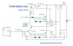
This amp makes use of dynamic expander character of mosfet in classB mode to deliver ultra fresh sound with opposite phase odd order harmonics.
Warning , the sound of this amplifier is addictive .
The input use Rush cascode. I use it for one of my pre-amps.
Some call it bastode . NAD3020 uses it also in low level. According to our historian PRR, he has a book dating the 60's where such circuit is described.The input use Rush cascode. I use it for one of my pre-amps.
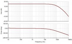
I had a go at simulating this topology with a few variations. I find the feedback network resistors R4/R6 can be increased in value by at least an order of magnitude, the gate biasing resistors R3/R7 can be increased and the constant current source reduced to match, again by at least an order of magnitude, and this seems to remove a strong peak in the frequency response at HF.
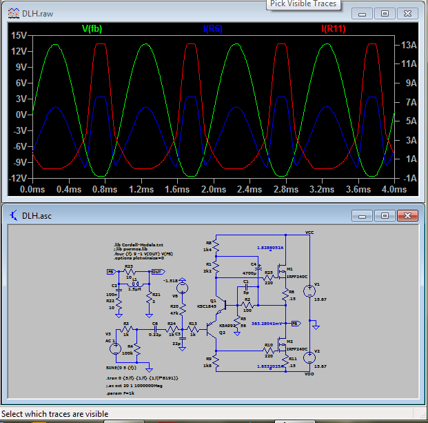
The distortion residual with negative feedback looks like mainly crossover distortion to me - certainly not the 3rd harmonic of the open loop.
The distortion residual with negative feedback looks like mainly crossover distortion to me - certainly not the 3rd harmonic of the open loop.
To design this amp you need to understand how it functions . The driver made of Rush cascade and CCS pours it's power to the load via zener , 220 ohms and two diodes . The current is sensed by the resistors and command the mosfet to pour it's current to the load and unload the class a driver. This type of amp is immune to crossover distortion as the class a amp fills the blanks while the outputs need time to switch on. On simulator with outputs biased just on cut off with leakage current has no crossover distortion at 100mw. But in real world the gate voltage of the outputs do not cutoff so sharply bellow 20ma . I could reduce it down to 5ma by 17ma on CCS , the sound is exactly the same as biased 120ma . Only by listening several days that 20ma bias by 20ma CCS I got the best fatigue free listening.
Last edited:
DLH has a fatal output mosfets cross conduction stating at input voltages ~> 1.5V RMS. Please check your circuit, I strongly suspect it has the same inherent flaw. I proposed addition of 1k8 to base of NPN, T5 in your case to contain the issue.
Last edited:
- Home
- Amplifiers
- Solid State
- ClassB+a mosfet amplifier