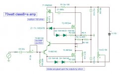
DHL suffers from low quiescent voltage Vce of NPN transistor , only 4volts. This fact limits the negative excursion to deliver only 3.8w for 8 ohms . I proposed several solutions by RC components , but not for the taste of Diego. In my circuit it is the zener diode resolves this problem .
LTspice stubbornly shows otherwise, kindly confirm or disagree with measurements. We do not want inadvertent but preventable fatal incidents to builds of your nice design in the field. I feel the same fix I gave to DLH is just as applicable to yours as well, in this case refer to 1k8 R1 at the base of Q1 of the second schematic. LTspice asc attached.... In my circuit it is the zener diode resolves this problem .
As the designer you should evaluate and modify the fix as you see fit.
Attachments
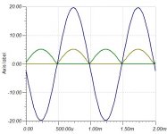
I don't see any wrong doing with Tina . The graph shows individual currents of the outputs with 20v peak 50w on 4 ohms. I ran this amp at full power for several hours thanks to comprehensive neighborhood who fled away , I would have remarked on amp meter or the 2A limiter of switching PSU would have activated.
Attachments
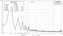
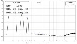
I concur to your finding up to 2.35V input. Problem starts to show up in LTspice on input > 2.35V (4.7Vpp, 1.66V RMS). The point where Vce of the NPN reach 0V on negative peaks. Here is output for 2.4V (1.7V RMS) input.
My proposed fix as shown should help protect the amp, along with a 1k input resistor to inadvertent high voltage on input and static electricity ~> 20V.
My proposed fix as shown should help protect the amp, along with a 1k input resistor to inadvertent high voltage on input and static electricity ~> 20V.
Attachments
Last edited:
Thank you very much for your attention. Indeed it gets hot on saturation. The remedy is to higher the zener to 17v , decrease the gain by replacing 330 ohms to 270, and adding Indra resistor of 68 ohms . With 3v input it saturates without cross conducting . I'll post the circuit when my Internet link gets faster.
Well I'm using slightly different MOSFET models, and a CCS in place of the depletion mode device, which could explain it.I don't have any HF peaking.
BTW the tempco of that depletion mode device is very high, it would make for wandering bias point I think.
As for "no crossover distortion", that's never possible in a class B design.
It is interesting that the fairly clear 3rd harmonic distortion open-loop pretty much vanishes when the loop is closed, leaving the crossover component visible. I need to do a bit more investigation and report back with my .asc file. I have a suspicion the 2nd feedback path may be important (100k DC path to input) - I think it needs decoupling to ground (I'll try injecting PSU ripple too)
A bit of concern on < 2V across the DN2540 CCS. You need to confirm proper operation in real circuit.... higher the zener to 17v ,...
The CCS can function down to 1.7v . At quiescent it has 3.6v and falls at saturation 2.18v min.A bit of concern on < 2V across the DN2540 CCS. You need to confirm proper operation in real circuit.
This amp is designed to function with switching power supply, one for each channel. The input capacitors filters the buzz. With 97db speaker my ear upon the diagram, I hear no any noise although the cheap PSU is rather noisy. You can ground 10uf on the center point of Vcc/2 adjust if necessary.Well I'm using slightly different MOSFET models, and a CCS in place of the depletion mode device, which could explain it.
BTW the tempco of that depletion mode device is very high, it would make for wandering bias point I think.
As for "no crossover distortion", that's never possible in a class B design.
It is interesting that the fairly clear 3rd harmonic distortion open-loop pretty much vanishes when the loop is closed, leaving the crossover component visible. I need to do a bit more investigation and report back with my .asc file. I have a suspicion the 2nd feedback path may be important (100k DC path to input) - I think it needs decoupling to ground (I'll try injecting PSU ripple too)
This amp makes use of dynamic expander character of mosfet in classB mode to deliver ultra fresh sound with opposite phase odd order harmonics.
Warning , the sound of this amplifier is addictive .
I am very happy that you have developed this beauty of amplifier, starting from the base of my modest DLH.
What is really attractive about these configurations is found in the distribution of the spectrum of its distortion. Something interesting encloses in its open-loop gain 😉.
Congratulations
Then you should be ok. 😉The CCS can function down to 1.7v . ...
I didn't want to bother you with amplifier issue when you have much more important to deal with.I am very happy that you have developed this beauty of amplifier, starting from the base of my modest DLH.
What is really attractive about these configurations is found in the distribution of the spectrum of its distortion. Something interesting encloses in its open-loop gain 😉.
Congratulations
This offspring of DLH is not intended to compete with number of zeros in distortion value. On the contrary it is intended to be nonlinear inversely to the speaker's to compensate it's compressive character . Dynamic expanders generate odd order harmonics of opposite phase to the fundemental as does this amp. I am not pioneering in this type of amplifier, Japanese audiophiles use triodes in class B since long time, and now pentodes wired in triode with more expanding character are used . The latest Luxman with push pull KT88 in triode, class B, delivers only 20W , when in class A UL , can advantageously . One can ask why not dynamic expender at low level ? Because the damping factor must also be variable with the level . The lowest distortion speaker I have seen, generates 0.1% 3rd order harmonic at 96db at 2m. Mine , home made 97db/w/m ,has 0.5% at 5w. This amp is intended to decrease such distortion.
Could you imagine ,that your ingenious class A circuit can be transformed into class AA?
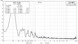
Latest version , direct input with distortion adjust 0.16% to 0.75%.
It is very strategic to try to minimize the acoustic distortion (which is the one that finally reaches our ears and the one I suppose must occur below perceivable levels), which does not necessarily imply achieving the lowest electrical distortions in the signal.
I have tried to minimize acoustic distortion, although with important results, within somewhat limited frequency and level ranges. Therefore, it is convenient to minimize acoustic distortion in sensitive ranges of the spectrum and in the frequency range where distortion cannot be minimized at all, ensure that they occur in less sensitive areas of the spectrum.
For example, in a woofer I could reduce the acoustic distortion from 1.64% to only 0.23% (keeping this reduction rate in the range of approximately 2 octaves). The electrical signal that the amplifier had to deliver to the speaker should be distorted in 2.66% (H2 in 2.56%, H3 in 0.72% and the subsequent ones around 0.003%).
It is usually easier to operate the speaker within its more linear range, where H2 appears mostly followed by a smaller proportion of H3. At that point, it has been easier for me to minimize acoustic distortion, even in a wider frequency range.
Attachments
Last edited:
The idea that you can cancel speaker non-linearity with a fixed circuit has limitations - the impedance of a speaker varies significantly with frequency across resonance, so the mapping between instantaneous cone position and instantaneous voltage is not straight-forward.
I suspect that across the resonant section of a speakers response you may make distortion worse. Hopefully away from resonance the relationship is more behaved and benefit is reliable for these frequencies - I'd err on the side of caution though, under compensation.
An interesting plot would be distortion (by harmonic) plotted across the speaker's full frequency range, and at several power levels. (Both with and without expanding amplification).
And intermodulation spectra would be interesting to measure too (and perhaps more relevant to human perception).
Its a complex story.
My feeling is that the way to do this stuff with rigour is digital pre-processing before a linear amp, programmed automatically using feedback from a high-grade measurement microphone and a long series of test tones. A complex model could be derived of the speaker's actual behaviour, leading to a cancellation filter tailored to the specific drivers.
Though there are many difficulties (its a non trivial mathematical task). If it was easy it there would be existent cheap technology to linearize speakers.
Do not take the curves that I have given as the complete history of the situation. It is obvious that it is much more complex than what I have introduced simply as dimensioning.
Even, everything changes if with the same amplifier we must simultaneously attack more than one transducer with their respective associated filters (changes in the phase).
Another possibility of minimizing acoustic distortion could occur in high excursion speakers, with current mode operation. Or, even, handling more than one technique at a time (pre distort electrically the signal to the speaker and current mode operation). When the excursion in the transducer is smaller (as in medium to high frequencies), the situation is less favorable to expect noticeable improvements.
Last edited:
Richard Marsh showed reduction from ~5% to >2% at 45 Hz, close to resonance @ 95dB by current feedback in Audio Amateur 1985 Marsh MFB-ckt-pdf and Marsh MFB_2.pdf... I suspect that across the resonant section of a speakers response you may make distortion worse. Hopefully away from resonance the relationship is more behaved and benefit is reliable for these frequencies - I'd err on the side of caution though, under compensation....
Do it multi amp, one amp for each driver, makes more sense. Use any trick you prefer. Partial cancellation is always better than none. 🙂... My feeling is that the way to do this stuff with rigour is digital pre-processing before a linear amp, programmed automatically using feedback from a high-grade measurement microphone and a long series of test tones. A complex model could be derived of the speaker's actual behaviour, leading to a cancellation filter tailored to the specific drivers.
Though there are many difficulties (its a non trivial mathematical task). If it was easy it there would be existent cheap technology to linearize speakers.
Last edited:
can we use irfp150?
It is identical to IRFZ44 but 175w vs 150w and 10 times more expensive from the same shop .
- Home
- Amplifiers
- Solid State
- ClassB+a mosfet amplifier